Hi Guys,
It's been a while since I spent time on the forum, but just because I am not posting doesn't mean I am not busy doing audio related things 8)
During the holidays I built my first preamp. When I say built, I mean that I designed the circuit and power supply from scratch, etched the boards, drilled the holes, soldered the components, tested everything, made some fixes where needed, stabilized the circuits, and mounted everything into some enclosures. It even works - sounds pretty good too :thumbs:
I was having some issues with the pot - channel tracking is pretty bad. So much so that I had to solder in a resistor onto one of the gangs just so things will be more reasonable. Even with this fix the damn pot is only *reasonable* for about a third of the total travel...
The thing is that I have been playing around with microcontrollers for a while now, and have always said that it will be reasonably easy to implement a microcontroller based relay switched stepped attenuator. Only that I never needed to actually do it until now. They say talk is cheap, so I decided it was time to come up with the the proof (of principle). This was pretty much done in a day and a half, and I even managed not to burn out anything :whistler:
Just to test things out, I used some Vero-board and only implemented 4 relays. Also implemented a small LCD display, and an IR Receiver module. I have a remote control here from an old DVD player, and just used that to generate the up / down IR signals for the test.
When I get around to making the real thing it will obviously be on an etched PCB, and will most likely implement 6 relays.
The relays are 12V DPDT, Bistable latching types with gold glad silver nickel contacts made specifically for small signal switching.
Because I have used 4 relays, and am working them in a binary system, I get a maximum of 16 distinct steps (in stereo) out of the 4. That's 00 through to 15.
Also, because this is a proof of principle build (a test really), I am using LEDs to show me which relays are switched and how. When this is converted to a volume control, the diodes will be replaced by discrete resistors.
Enough talk already! Show the pictures!!!!
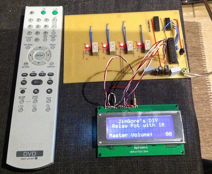
Here you can see the setup showing 00 volume (all 4 LEDs are RED). A Red LED indicates a 0 position (off if you prefer), and a Green LED indicates a 1 position (ON). Therefore all 4 LEDs being RED indicate the binary code 0000 = decimal 0:
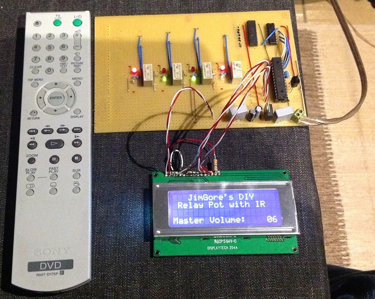
Here you can see the setup showing 06 volume. If you check the illuminated LEDs, and remember a RED = 0, and a GREEN = 1, then you have:
RED / GREEN / GREEN / RED = 0110 Binary = 06 Decimal:
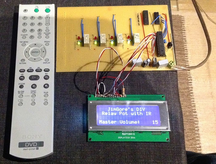
And finally here you can see the setting at 15 volume. All the LEDS are now green, so that's 1111 binary = 15 decimal")
Out of interest - I mentioned earlier that the relays I am using are Bistable latching types. That means that after I switch the relay, I actually disconnect the power from it completely. This is because it will "hold" itself at the position I last switched it to. What's also nice about that is the fact that you don't have any 12V DC being constantly applied to the relay coils. The hope is that this will help keep the actual audio signal clean.
At this point the entire thing runs on it's own - the two wires you see coming off the bottom right of the PCB are just supplying 12V DC to the board. I have programmed all the intelligence / logic onto the microprocessor, so I am very happy to say that I feel this is a success story.
Now I just need to get working on my version 2.0 preamp into which this thing will go and we are in business!
What do I have planned for the next version?
- 64 step relay based attenuator. My current preamp has 128 steps in 0.5dB incremements, and to be honest that's driving me a bit crazy. I will do the 64 steps in 1.5dB increments.
- Perhaps 3 or 4 inputs, also relay based.
- Remote controlled
- Rotary encoder style volume control knob and input selector knobs
I know there will more than likely be some teething issues in the proper version, especially foreseeing these with relation to transients caused by relay switching, but hopefully those will be reasonably easily resolved. Time will tell.
So, what do you think? Does it have some potential? Like it / hate it?
Cheers,
Ian.
It's been a while since I spent time on the forum, but just because I am not posting doesn't mean I am not busy doing audio related things 8)
During the holidays I built my first preamp. When I say built, I mean that I designed the circuit and power supply from scratch, etched the boards, drilled the holes, soldered the components, tested everything, made some fixes where needed, stabilized the circuits, and mounted everything into some enclosures. It even works - sounds pretty good too :thumbs:
I was having some issues with the pot - channel tracking is pretty bad. So much so that I had to solder in a resistor onto one of the gangs just so things will be more reasonable. Even with this fix the damn pot is only *reasonable* for about a third of the total travel...
The thing is that I have been playing around with microcontrollers for a while now, and have always said that it will be reasonably easy to implement a microcontroller based relay switched stepped attenuator. Only that I never needed to actually do it until now. They say talk is cheap, so I decided it was time to come up with the the proof (of principle). This was pretty much done in a day and a half, and I even managed not to burn out anything :whistler:
Just to test things out, I used some Vero-board and only implemented 4 relays. Also implemented a small LCD display, and an IR Receiver module. I have a remote control here from an old DVD player, and just used that to generate the up / down IR signals for the test.
When I get around to making the real thing it will obviously be on an etched PCB, and will most likely implement 6 relays.
The relays are 12V DPDT, Bistable latching types with gold glad silver nickel contacts made specifically for small signal switching.
Because I have used 4 relays, and am working them in a binary system, I get a maximum of 16 distinct steps (in stereo) out of the 4. That's 00 through to 15.
Also, because this is a proof of principle build (a test really), I am using LEDs to show me which relays are switched and how. When this is converted to a volume control, the diodes will be replaced by discrete resistors.
Enough talk already! Show the pictures!!!!
Here you can see the setup showing 00 volume (all 4 LEDs are RED). A Red LED indicates a 0 position (off if you prefer), and a Green LED indicates a 1 position (ON). Therefore all 4 LEDs being RED indicate the binary code 0000 = decimal 0:
Here you can see the setup showing 06 volume. If you check the illuminated LEDs, and remember a RED = 0, and a GREEN = 1, then you have:
RED / GREEN / GREEN / RED = 0110 Binary = 06 Decimal:
And finally here you can see the setting at 15 volume. All the LEDS are now green, so that's 1111 binary = 15 decimal
Out of interest - I mentioned earlier that the relays I am using are Bistable latching types. That means that after I switch the relay, I actually disconnect the power from it completely. This is because it will "hold" itself at the position I last switched it to. What's also nice about that is the fact that you don't have any 12V DC being constantly applied to the relay coils. The hope is that this will help keep the actual audio signal clean.
At this point the entire thing runs on it's own - the two wires you see coming off the bottom right of the PCB are just supplying 12V DC to the board. I have programmed all the intelligence / logic onto the microprocessor, so I am very happy to say that I feel this is a success story.
Now I just need to get working on my version 2.0 preamp into which this thing will go and we are in business!
What do I have planned for the next version?
- 64 step relay based attenuator. My current preamp has 128 steps in 0.5dB incremements, and to be honest that's driving me a bit crazy. I will do the 64 steps in 1.5dB increments.
- Perhaps 3 or 4 inputs, also relay based.
- Remote controlled
- Rotary encoder style volume control knob and input selector knobs
I know there will more than likely be some teething issues in the proper version, especially foreseeing these with relation to transients caused by relay switching, but hopefully those will be reasonably easily resolved. Time will tell.
So, what do you think? Does it have some potential? Like it / hate it?
Cheers,
Ian.