Those of you who know me will know that I am not the biggest fan of transmission line type speakers. Not for any reason except preference - I have yet to hear a TL that I really like.
That was the case until last week Monday. I went to visit a friend of mine who had built a TL, and I loved it! He built a 3-way using a 6" high efficiency mid/bass driver, a 4" midrange, and a tweeter. The thing that got me thinking was the bass response he managed to get out of that 6" HE driver. Nothing that will blow your socks off, but seriously great for a HE driver. Now, I am sure you all know that high efficiency does not really have much bass, even when the cabinets become excessively large (think about my current HE speakers - they are huge, and still have very little bass).
So, after hearing my friend's system I decided to re-evaluate my stance on TL designs and do some experimentation.
After doing quite a bit of research on the subject, I decided to build what can only be called a Troels clone. I think he had some very good ideas with his TQWT build using a HE mid/bass driver and a standard dome tweeter mounted on a waveguide. I remember enquiring about his TQWT kit some time ago, and the cost was prohibitive. Cannot remember exactly, but it was around R 13,000 or something similar. That is quite hectic for a 2 way speaker!
I am using this build for research. In this light I am only building one speaker as a proof of principle.
The objectives for this build are:
1. Get reasonable bass out of an 8" HE driver...
2. In a cabinet that is of a reasonable size...
3. Without using active components to EQ or boost the bass...
4. And match it with a standard dome tweeter
5. Finally, it must sound good! Most important one of all.
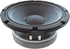
I did some homework on suitable 8" high efficiency drivers, and decided on the Beyma 8G40.
Herewith the specsheet: http://profesional.beyma.com/ingles/pdf/8G40.pdf
For the tweeter, I have a number of SB Acoustics SB26STCN-C000 4 ohm tweeters.
Specsheet: https://www.madisound.com/store/manuals/SB26STCN-C000--%20pdf.jpg

Now, we need to try and match up the sensitivity of the tweeter with that of the HE Beyma driver. The Beyma is 95dB, and the SB Acoustic is 92dB. I don't like padding a bass speaker, so I will need to get creative here. One thing I am doing is loading the tweeter in a waveguide which should give me some additional sensitivity. The baffle-step compensation should taper the Beyma down a bit as well. If that still isn't good enough I have some other tricks up my sleeve")
Onto the photos then...
The cabinet is 230mm wide, by 370mm deep, by 900mm high. The line is about 1.7m long. In theory this should result in a line frequency of around 50Hz. In practice, the damping material as well as the 180 degree bend in the line will most probably make this line function at around 41Hz (all in theory of course)

The Beyma driver needs 11mm worth of recess, which in a 16mm baffle will not leave enough "meat" for the screws to hold onto well. I therefore decided to make an additional baffle.

Now, my mind did not allow me to simply make a rectangular baffle, so some functional creativity was required:

The two clamps in the picture are holding the baffle to a perfectly straight and square piece of wood which rests on top of my table saw's guide:

You can see where this is going now:

And that is how you do a 11 degree cut on the edge of a piece of MDF:

I did a couple more of those cuts, then smoothed the edges over with sandpaper:

Next I glued the baffle into place, and added some bracing into the cabinet:

I had a lapse of concentration here and routed too far, so the clamp is holding a small piece of wood which I glued back on:

This is how it looks - quite good even if I have to say so myself. Much better than just gluing an extra piece of wood on.

Routing the tweeter hole, I went through a large section of the 45degree piece at the end of the line. You need a really long router bit for this because my baffle is 32mm, the circle jig is another 16mm thick, and I had to get through all of that + another 20mm worth of brace. I use a extra long 12mm machinist slot-drill in my router for that job. Here you can see it next to a 1/2 inch shank, 16mm diameter router bit:

Next, I spent some time on the lathe with a 130mm diameter billit of aluminium. This is the result of many hours worth of machining:

Another angle:

Here you can see the back. Notice how I am attaching this to the cabinet: no screws visible from the front! If you look closely at the waveguide opening, you will see a raised bit on the lip. I did that to allow me to get right inside the tweeter flange which has a small round-over on it.

Tweeter mounted:

Waveguide in the baffle:

Close-up of the throat section and the fit to the tweeter:

The view from inside the cabinet:

The left side-panel still needs to be fit, but this is what it looks like as of this evening. The polished aluminium looks quite pornstar. Too bling for me, but it will work well enough to measure with:

This is the mouth of the line. The entire bottom of the cabinet is the mouth area. Side panel is only clamped on for the photo - no glue.

That's all the progress I made over the weekend. Following, I will add the damping material into the cabinet, then glue the side panel on. After that, it is measurement time!
Have a good evening further.
Regards,
Ian.
That was the case until last week Monday. I went to visit a friend of mine who had built a TL, and I loved it! He built a 3-way using a 6" high efficiency mid/bass driver, a 4" midrange, and a tweeter. The thing that got me thinking was the bass response he managed to get out of that 6" HE driver. Nothing that will blow your socks off, but seriously great for a HE driver. Now, I am sure you all know that high efficiency does not really have much bass, even when the cabinets become excessively large (think about my current HE speakers - they are huge, and still have very little bass).
So, after hearing my friend's system I decided to re-evaluate my stance on TL designs and do some experimentation.
After doing quite a bit of research on the subject, I decided to build what can only be called a Troels clone. I think he had some very good ideas with his TQWT build using a HE mid/bass driver and a standard dome tweeter mounted on a waveguide. I remember enquiring about his TQWT kit some time ago, and the cost was prohibitive. Cannot remember exactly, but it was around R 13,000 or something similar. That is quite hectic for a 2 way speaker!
I am using this build for research. In this light I am only building one speaker as a proof of principle.
The objectives for this build are:
1. Get reasonable bass out of an 8" HE driver...
2. In a cabinet that is of a reasonable size...
3. Without using active components to EQ or boost the bass...
4. And match it with a standard dome tweeter
5. Finally, it must sound good! Most important one of all.
I did some homework on suitable 8" high efficiency drivers, and decided on the Beyma 8G40.
Herewith the specsheet: http://profesional.beyma.com/ingles/pdf/8G40.pdf
For the tweeter, I have a number of SB Acoustics SB26STCN-C000 4 ohm tweeters.
Specsheet: https://www.madisound.com/store/manuals/SB26STCN-C000--%20pdf.jpg
Now, we need to try and match up the sensitivity of the tweeter with that of the HE Beyma driver. The Beyma is 95dB, and the SB Acoustic is 92dB. I don't like padding a bass speaker, so I will need to get creative here. One thing I am doing is loading the tweeter in a waveguide which should give me some additional sensitivity. The baffle-step compensation should taper the Beyma down a bit as well. If that still isn't good enough I have some other tricks up my sleeve
Onto the photos then...
The cabinet is 230mm wide, by 370mm deep, by 900mm high. The line is about 1.7m long. In theory this should result in a line frequency of around 50Hz. In practice, the damping material as well as the 180 degree bend in the line will most probably make this line function at around 41Hz (all in theory of course)
The Beyma driver needs 11mm worth of recess, which in a 16mm baffle will not leave enough "meat" for the screws to hold onto well. I therefore decided to make an additional baffle.
Now, my mind did not allow me to simply make a rectangular baffle, so some functional creativity was required:
The two clamps in the picture are holding the baffle to a perfectly straight and square piece of wood which rests on top of my table saw's guide:
You can see where this is going now:
And that is how you do a 11 degree cut on the edge of a piece of MDF:
I did a couple more of those cuts, then smoothed the edges over with sandpaper:
Next I glued the baffle into place, and added some bracing into the cabinet:
I had a lapse of concentration here and routed too far, so the clamp is holding a small piece of wood which I glued back on:
This is how it looks - quite good even if I have to say so myself. Much better than just gluing an extra piece of wood on.
Routing the tweeter hole, I went through a large section of the 45degree piece at the end of the line. You need a really long router bit for this because my baffle is 32mm, the circle jig is another 16mm thick, and I had to get through all of that + another 20mm worth of brace. I use a extra long 12mm machinist slot-drill in my router for that job. Here you can see it next to a 1/2 inch shank, 16mm diameter router bit:
Next, I spent some time on the lathe with a 130mm diameter billit of aluminium. This is the result of many hours worth of machining:
Another angle:
Here you can see the back. Notice how I am attaching this to the cabinet: no screws visible from the front! If you look closely at the waveguide opening, you will see a raised bit on the lip. I did that to allow me to get right inside the tweeter flange which has a small round-over on it.
Tweeter mounted:
Waveguide in the baffle:
Close-up of the throat section and the fit to the tweeter:
The view from inside the cabinet:
The left side-panel still needs to be fit, but this is what it looks like as of this evening. The polished aluminium looks quite pornstar. Too bling for me, but it will work well enough to measure with:
This is the mouth of the line. The entire bottom of the cabinet is the mouth area. Side panel is only clamped on for the photo - no glue.
That's all the progress I made over the weekend. Following, I will add the damping material into the cabinet, then glue the side panel on. After that, it is measurement time!
Have a good evening further.
Regards,
Ian.