So with the advent of building my own 'audiophile' switch, it made sense to look further upstream in the network especially since other folks reported positive findings.
From my internet router to the streamer are three switches, with the last in the chain being my own. No way will I put big money in the other two upstream switches and no power-sapping linear power supplies either, but some cost-effective treatments like what Croak used to do would be fun.
So, two appropriate switches were identified that had sufficient internal space, no fans, established reliability, low power consumption, low cost and unmanaged. Some people go for big Cisco managed switches that IMO is the complete wrong way to do it, unless the management features are actually required. Then they complain how difficult and expensive it is to mod.
I settled on a Netgear GS308 8-port and a D-Link DGS-1016D 16-port. The first is powered by a 12V wall wart and the other AC.
For both I designed a little PCB housing a low-jitter oscillator powered by a very low-noise linear regulator. For the 16-port I also designed a passive DC post-filter PCB, with all kinds of filtering across various frequency bands. Not nearly as good as a regulated power supply, but a good step up.
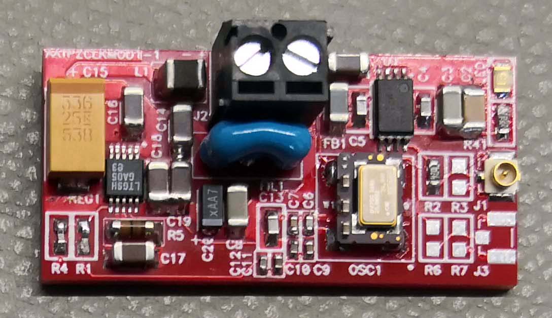
The clock PCB is shown below, tiny but effective. For the clock connection to the switch mainboard, most use coax or twisted pair (or just two wires). Coax typically is best, but most use way too thick cable like RG58 that eventually is more pigtail than coax and almost as good as just zipcord. I opted for u.fl connectors and cables. Both are tiny and ideal for modding, not to mention cheap. It's commonly used for GPS and wifi antennas and effective up to 6GHz. The catch is limited mating cycles before it breaks, which is no problem. After the oscillator is a dual fanout buffer to drive two clock outputs individually.
Here's the clock PCB, measuring only 37 x 18mm. The u.fl connector is at the right.
The 16port has two switch IC's, each with its own crystal. These crystals and their associated components got removed and replaced with actually putting another u.fl connector on the mainboard. Electrically it's still similar to using a pigtail with bare wires, but a little better as I made the loop connection to the closest ground pad very small. The heatsinks had to be unsoldered but fortunately it was not too hard.
No-name mainboard electrolytics got replaced with long-life Nichicons and some 0R resistors replaced with ferrite beads.
Before and after shots:
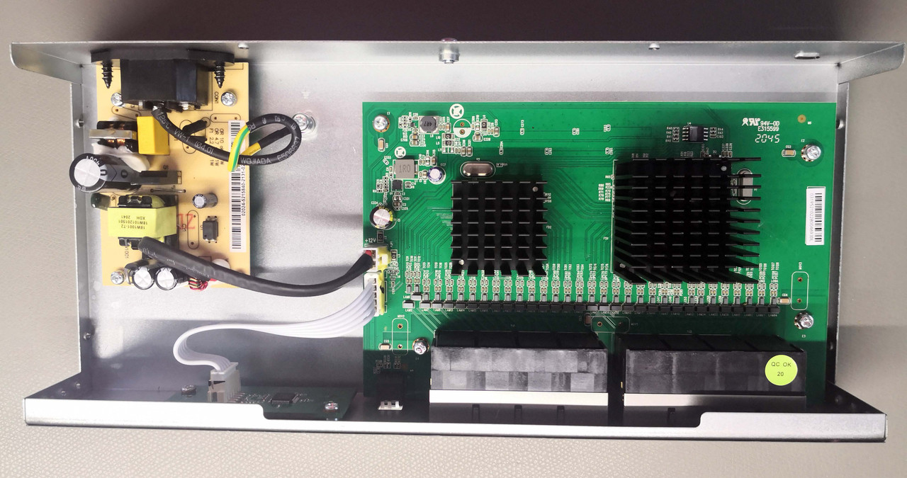
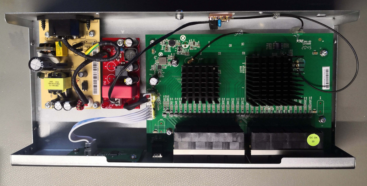
In the latter the DC filter PCB can be seen between the SMPS and switch, and the clock PCB mounted vertically.
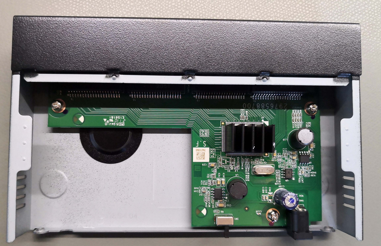
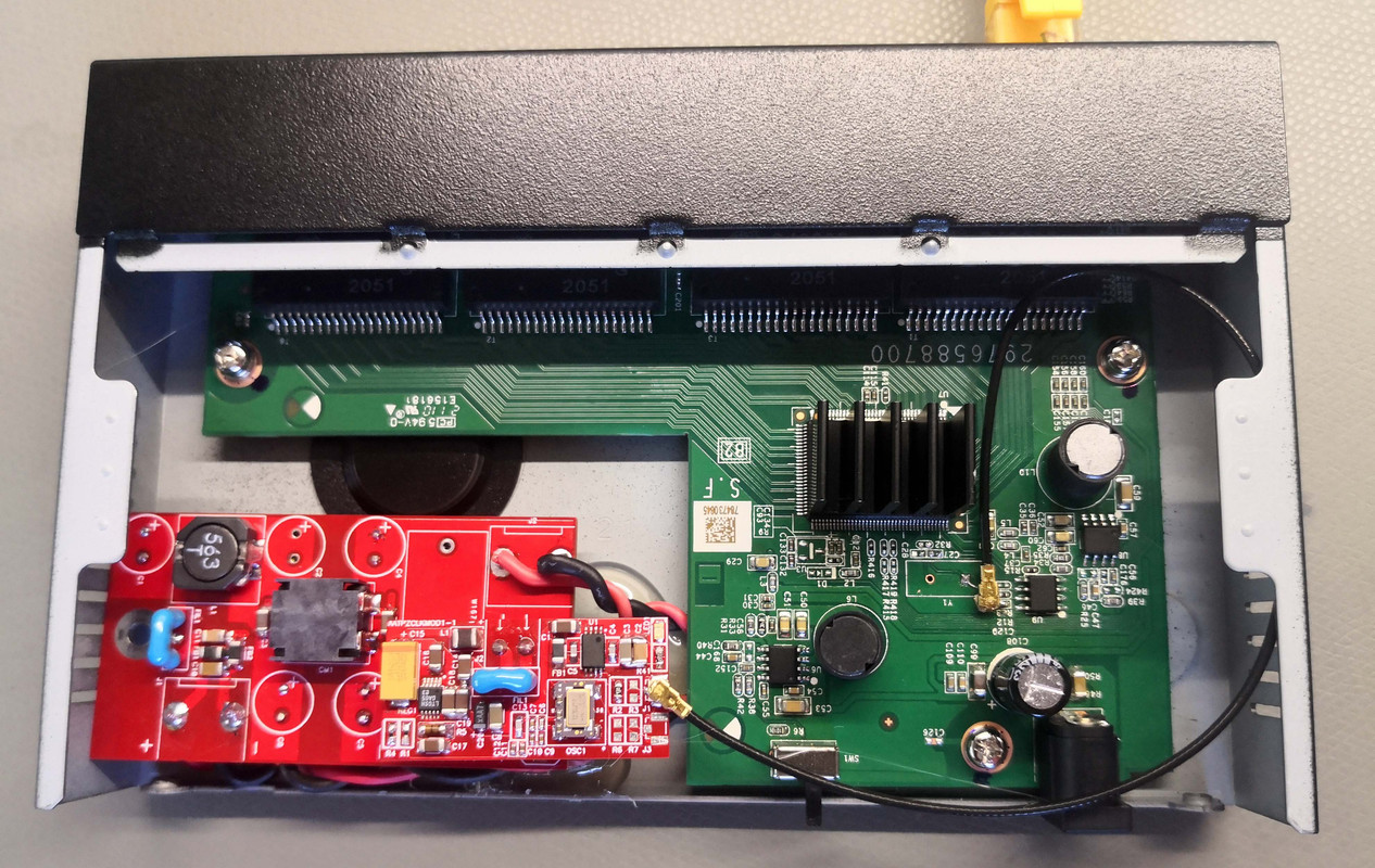
The 8port is known to be very reliable except for input caps failing, so it got replaced. The same method got used as with the 16-port for the clock. Originally I didn't intend to DC-filter but since there was enough space and I had spare PCB's, why not. The connection after the barrel jack got broken and fed via the DC filter back to the switch and clock module. Some additions also got made in critical places by adding quality ceramic capacitors. The electrolytic capacitors of the DC module are mounted horizontally on the bottom and the large film cap omitted because of the height restriction.
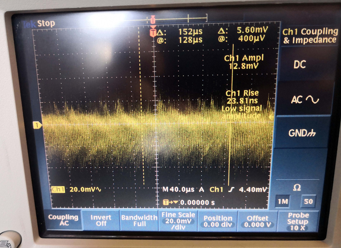
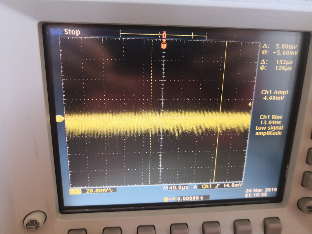
Measuring noise ideally needs a spectrum analyzer that is hogged by a colleague, but with a scope one can get some snapshots of certain frequency ranges. Here's the before and after of the 12V line of the Netgear.
Since my streaming setup is not running yet I have of the actual performance impact, but it makes me sleep better at night and was a fun and low-cost exercise. I do have a feeling that the warranty might be slightly void though..
From my internet router to the streamer are three switches, with the last in the chain being my own. No way will I put big money in the other two upstream switches and no power-sapping linear power supplies either, but some cost-effective treatments like what Croak used to do would be fun.
So, two appropriate switches were identified that had sufficient internal space, no fans, established reliability, low power consumption, low cost and unmanaged. Some people go for big Cisco managed switches that IMO is the complete wrong way to do it, unless the management features are actually required. Then they complain how difficult and expensive it is to mod.
I settled on a Netgear GS308 8-port and a D-Link DGS-1016D 16-port. The first is powered by a 12V wall wart and the other AC.
For both I designed a little PCB housing a low-jitter oscillator powered by a very low-noise linear regulator. For the 16-port I also designed a passive DC post-filter PCB, with all kinds of filtering across various frequency bands. Not nearly as good as a regulated power supply, but a good step up.
The clock PCB is shown below, tiny but effective. For the clock connection to the switch mainboard, most use coax or twisted pair (or just two wires). Coax typically is best, but most use way too thick cable like RG58 that eventually is more pigtail than coax and almost as good as just zipcord. I opted for u.fl connectors and cables. Both are tiny and ideal for modding, not to mention cheap. It's commonly used for GPS and wifi antennas and effective up to 6GHz. The catch is limited mating cycles before it breaks, which is no problem. After the oscillator is a dual fanout buffer to drive two clock outputs individually.
Here's the clock PCB, measuring only 37 x 18mm. The u.fl connector is at the right.
The 16port has two switch IC's, each with its own crystal. These crystals and their associated components got removed and replaced with actually putting another u.fl connector on the mainboard. Electrically it's still similar to using a pigtail with bare wires, but a little better as I made the loop connection to the closest ground pad very small. The heatsinks had to be unsoldered but fortunately it was not too hard.
No-name mainboard electrolytics got replaced with long-life Nichicons and some 0R resistors replaced with ferrite beads.
Before and after shots:
In the latter the DC filter PCB can be seen between the SMPS and switch, and the clock PCB mounted vertically.
The 8port is known to be very reliable except for input caps failing, so it got replaced. The same method got used as with the 16-port for the clock. Originally I didn't intend to DC-filter but since there was enough space and I had spare PCB's, why not. The connection after the barrel jack got broken and fed via the DC filter back to the switch and clock module. Some additions also got made in critical places by adding quality ceramic capacitors. The electrolytic capacitors of the DC module are mounted horizontally on the bottom and the large film cap omitted because of the height restriction.
Measuring noise ideally needs a spectrum analyzer that is hogged by a colleague, but with a scope one can get some snapshots of certain frequency ranges. Here's the before and after of the 12V line of the Netgear.
Since my streaming setup is not running yet I have of the actual performance impact, but it makes me sleep better at night and was a fun and low-cost exercise. I do have a feeling that the warranty might be slightly void though..