Greetings
Had a lightbulb moment today while trying to figure out a way to make some sockets to connect a phono cartridge to the business end of the tonearm wiring. This could belong in the DIY section, but its exclusively related to Vinyl, hence its here for now and Im hoping that it doesnt dissappear into the depths.
I looked into making some sockets using the pins from male D-Type connectors. These are high quality, data/computer grade pins, and some may even be gold plated. With this idea, you may realise other similar materials that would yield same or better results. The only drawback is that the pins that I have trialled are slightly magnetic, ie they have some quantity of iron or steel in them, and other materials like brass or silver may be ideal if similar can be found, or if non-magnetic D-Type connectors/pins exist, that would be great.
I figured that the price of a jumper set of four socket connectors was way overpriced for what they are for the low end of the market, and wanted something easy, cost effective and convenient to make with readily available items and simple tools.
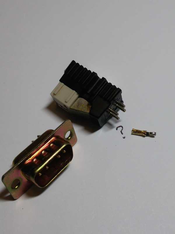
Picture One
Heres a standard D-Type male connector, with a completed pin socket next to the cartridge ( Philips GP371...opinions on this cart please ! This came off a TD150mk2). I stripped a 9pin connector for this, but any of the other sizes ( 25pin / 15 pin etc) will be fine as well. More to follow in the next picture.
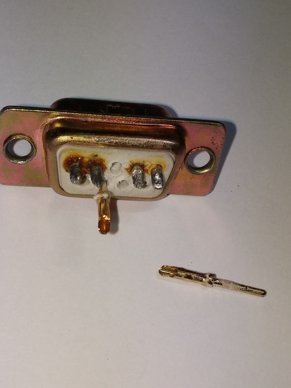
Picture Two
Only the unsoldered pins are useable, as the visible hollow is going to become the socket for the cartridge pin. I used a hot soldering iron tip held in place from the front side of the plug, and slowly slid out the useable pins after melting the plastic holding the pins in place. An extracted pin is visible. I needed four pins for this project. You can get nine pins from an unused D-Type connector which will make up four double socket jumpers for a cartridge-to-headshell connection with one spare pin left over.
The nice thing about these pins is that it is entirely one piece of metal, there is no physical joint between the hollow section and the shaft at the back.
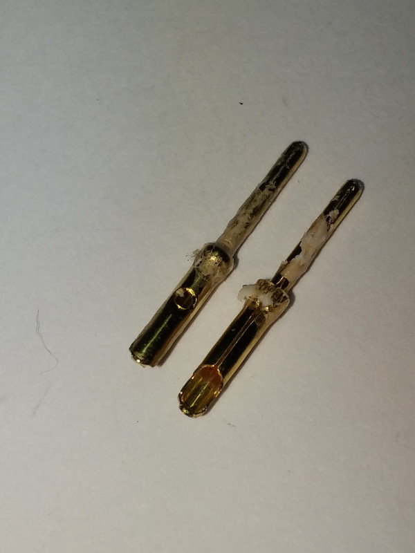
Picture Three
The two sides of the pin, still uncleaned with some melted plastic from the connector that is scraped off easily with a craft knife.
Notice in the upper pin, there is a hole. This is actually a nib of metal that was pressed into the hollow of the pin. This bump of metal now on the inside of the tube needs to be knocked back out so that the hollow can accomodate the cartridge pin.
This is achieved by slowly splitting apart the pin from its top side, along the seam ( bottom pin in pic). I used a sharp knife to get an initial gap in the seam before using a jewellers screwdriver to spread the seam about 1mm wide and then used the same driver hammered with a small piece of wood against the inner metal bump to flatten the bump back out.
Picture Four
An example of a completed pin, but the aim of this picture is to show the safe resizing of the hollow section (after knocking the bump of metal back out) by using a toothpick as a former when gently crimping the socket back into shape. At this stage you can test-fit the socket to a pin on the cartridge as shown, this is where the sizing needs to be tweaked for a snug fit.
Picture Five
The two upper pins are the original examples as extracted. The third pin from the top is a completed pin that has had the cupped-scoop at the front cut away, its shaft at the back trimmed to size, and has been tinned for the wire connection. The pin at the bottom is used to show exclusively how the shaft is flattened (using a small pliers or vicegrip) at the back to provide a flat, good contact surface for the solder joint. This flattening was done on pin three, but not visible due to the solder joint.
Note the little black band in front of the solder joint....this is some sewing cotton/polyester blend that was wrapped around at that point to form a barrier to any solder that may try to run into the socket/hollow during the tinning process. You can leave it in place ( it melts into a plastic band) as the wire still needs to be soldered onto this now.
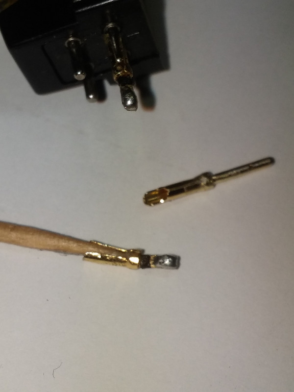
Picture Six
A completed pin fitted to a cartridge.
The only concern I have is that Im not certain if these pin sockets have to be non-ferrous, due to any possible issues with the moving magnet cartridge. However there are other sources of such non-ferrous material, one is the hollow brass pins from expired fluorescent lamps, the likes of the PL9 etc. These can be removed easily and repurposed here, and may even be suitable for making tiny rivets, all of which I want to explore sometime.
Four of these pins take about 40 minutes to make. I hope you enjoyed this article, and Im looking forward to suggestions and alternate materials and other DIY ideas for this.
Thank You
Marantz123.
Had a lightbulb moment today while trying to figure out a way to make some sockets to connect a phono cartridge to the business end of the tonearm wiring. This could belong in the DIY section, but its exclusively related to Vinyl, hence its here for now and Im hoping that it doesnt dissappear into the depths.
I looked into making some sockets using the pins from male D-Type connectors. These are high quality, data/computer grade pins, and some may even be gold plated. With this idea, you may realise other similar materials that would yield same or better results. The only drawback is that the pins that I have trialled are slightly magnetic, ie they have some quantity of iron or steel in them, and other materials like brass or silver may be ideal if similar can be found, or if non-magnetic D-Type connectors/pins exist, that would be great.
I figured that the price of a jumper set of four socket connectors was way overpriced for what they are for the low end of the market, and wanted something easy, cost effective and convenient to make with readily available items and simple tools.
Picture One
Heres a standard D-Type male connector, with a completed pin socket next to the cartridge ( Philips GP371...opinions on this cart please ! This came off a TD150mk2). I stripped a 9pin connector for this, but any of the other sizes ( 25pin / 15 pin etc) will be fine as well. More to follow in the next picture.
Picture Two
Only the unsoldered pins are useable, as the visible hollow is going to become the socket for the cartridge pin. I used a hot soldering iron tip held in place from the front side of the plug, and slowly slid out the useable pins after melting the plastic holding the pins in place. An extracted pin is visible. I needed four pins for this project. You can get nine pins from an unused D-Type connector which will make up four double socket jumpers for a cartridge-to-headshell connection with one spare pin left over.
The nice thing about these pins is that it is entirely one piece of metal, there is no physical joint between the hollow section and the shaft at the back.
Picture Three
The two sides of the pin, still uncleaned with some melted plastic from the connector that is scraped off easily with a craft knife.
Notice in the upper pin, there is a hole. This is actually a nib of metal that was pressed into the hollow of the pin. This bump of metal now on the inside of the tube needs to be knocked back out so that the hollow can accomodate the cartridge pin.
This is achieved by slowly splitting apart the pin from its top side, along the seam ( bottom pin in pic). I used a sharp knife to get an initial gap in the seam before using a jewellers screwdriver to spread the seam about 1mm wide and then used the same driver hammered with a small piece of wood against the inner metal bump to flatten the bump back out.
Picture Four
An example of a completed pin, but the aim of this picture is to show the safe resizing of the hollow section (after knocking the bump of metal back out) by using a toothpick as a former when gently crimping the socket back into shape. At this stage you can test-fit the socket to a pin on the cartridge as shown, this is where the sizing needs to be tweaked for a snug fit.
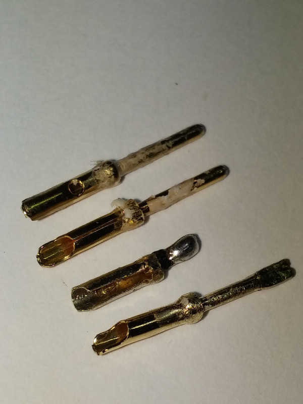
Picture Five
The two upper pins are the original examples as extracted. The third pin from the top is a completed pin that has had the cupped-scoop at the front cut away, its shaft at the back trimmed to size, and has been tinned for the wire connection. The pin at the bottom is used to show exclusively how the shaft is flattened (using a small pliers or vicegrip) at the back to provide a flat, good contact surface for the solder joint. This flattening was done on pin three, but not visible due to the solder joint.
Note the little black band in front of the solder joint....this is some sewing cotton/polyester blend that was wrapped around at that point to form a barrier to any solder that may try to run into the socket/hollow during the tinning process. You can leave it in place ( it melts into a plastic band) as the wire still needs to be soldered onto this now.
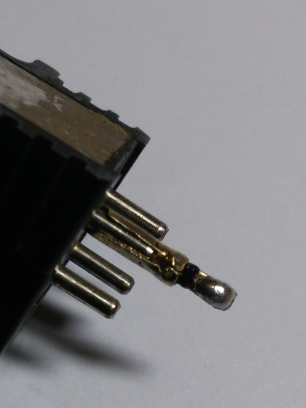
Picture Six
A completed pin fitted to a cartridge.
The only concern I have is that Im not certain if these pin sockets have to be non-ferrous, due to any possible issues with the moving magnet cartridge. However there are other sources of such non-ferrous material, one is the hollow brass pins from expired fluorescent lamps, the likes of the PL9 etc. These can be removed easily and repurposed here, and may even be suitable for making tiny rivets, all of which I want to explore sometime.
Four of these pins take about 40 minutes to make. I hope you enjoyed this article, and Im looking forward to suggestions and alternate materials and other DIY ideas for this.
Thank You
Marantz123.