WARNING: LARGE PICTURES
For anyone interested in the repair & modification process of a Meridian 568: I've taken some pictures during the process, here they are with some comments.
[not sure if this is the right category, mods please assist if necessary]
Recently I bought the 568, only to discover its right rear analog output channel occasionally popped with a large DC offset, followed by approx 12dB attenuation of the actual content and a lot of random noise superimposed on it (no hard feelings to the original owner, who only used it as a 2ch DAC/pre).
After initial sighs (this is after all the SEVENTH processor I bought that had/developed problems!), I opened her up and began probing.
What made the debug process particularly difficult was that the problem only sporadically occurs, often only after many hours of use. By the time the scope probes are going in, the problem has already disappeared again.
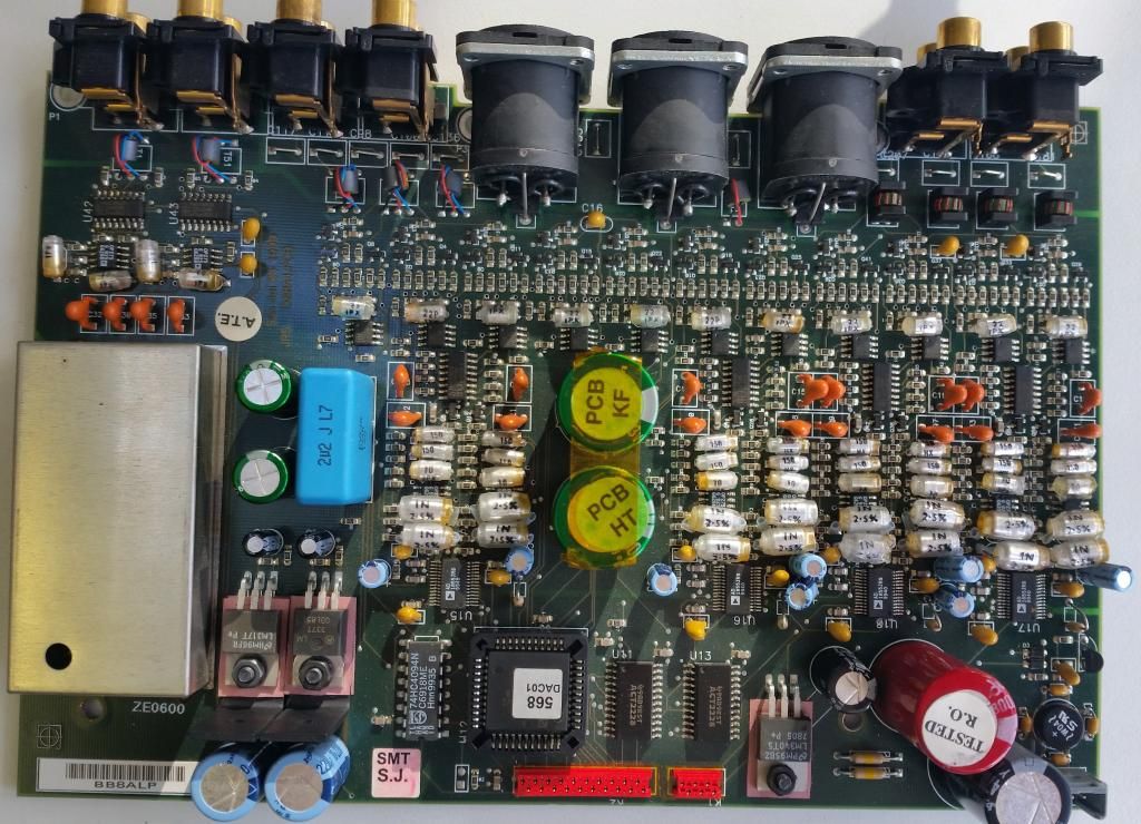
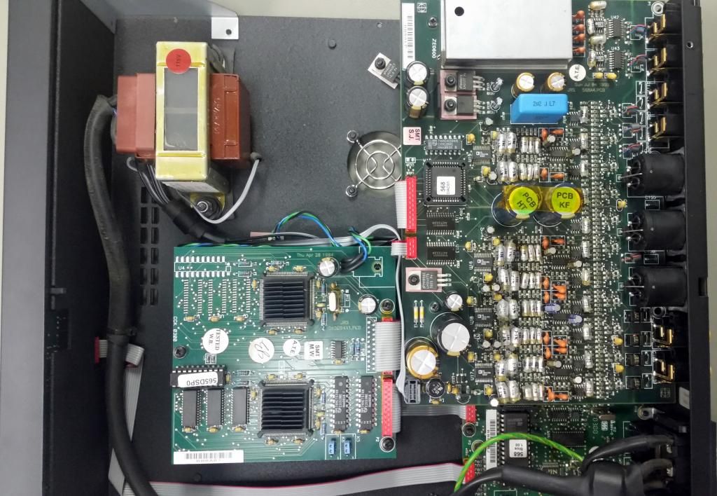
First step therefore was to figure out what goes on in the circuit:
We have one stereo AD1855 DAC per set of two channels, hard-configured for 44.1kHz sample rate. This DAC isn't bad at all even by modern standards, except for its digital filter being a tad behind.
After the DAC there is a summing amplifier for the differential DAC voltage outputs, not too different from the datasheet app note but with the difference that it uses a second opamp as virtual ground.
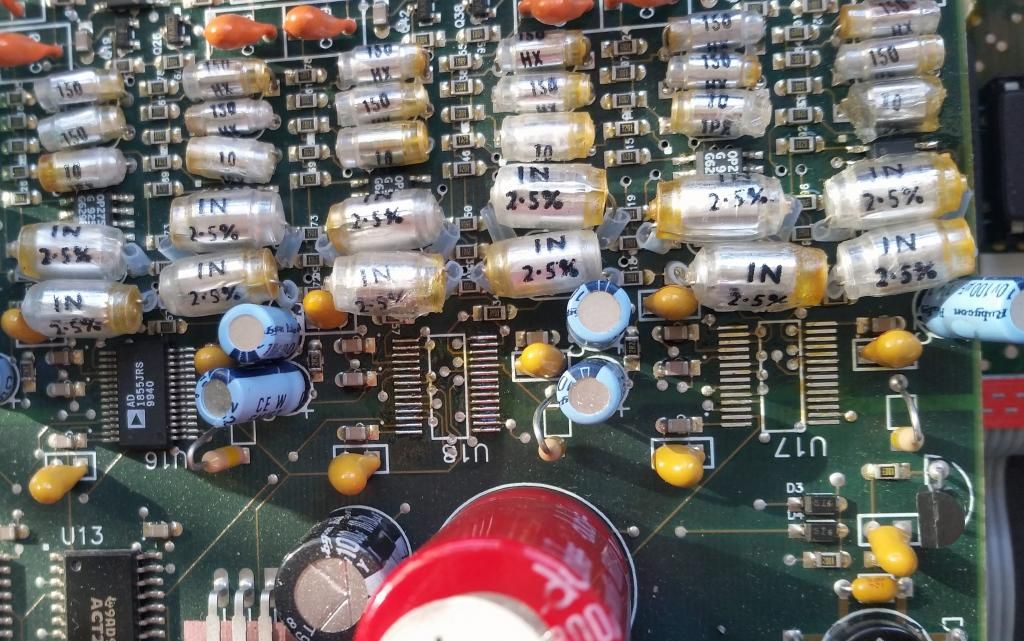
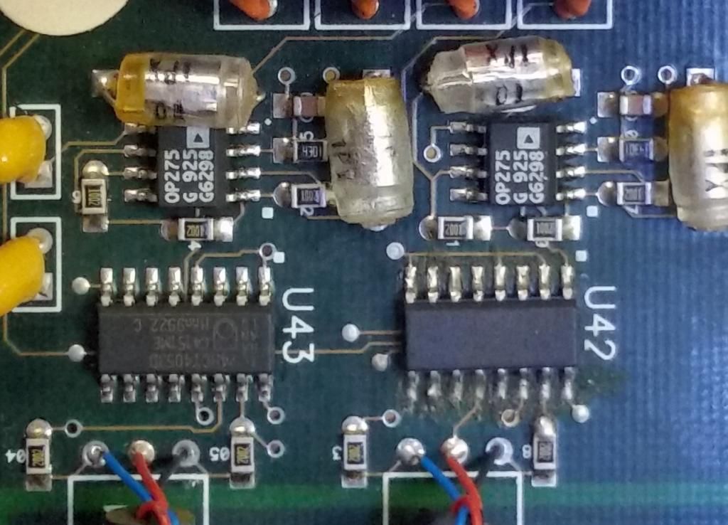
Filter caps are polystyrene; great for the application but I have my doubts whether the large packages and long lead inductance don't negate the advantage. They certainly made debugging a pain. The opamp for the virtual ground driver and summing amp per channel is a dual AD OP275 - not bad at all.
Following this, there is a series DC block with back-to-back tantalum capacitors (not great but oh well), then a crude kind of 4-bit progammable gain amplifier using a 74HCT4052D mux, then a gain stage with a single OPA134, and lastly a simple discrete BJT push-pull amplifier. This is probably to reduce the output impedance and add some current gain.
The front three channels have differential outputs; I didn't check any of that but I guess after the gain amplifier there's another inverting stage.
After the gain stage there's a split in the ground planes, and then the output connectors are coupled with common-mode chokes. I'm not sure whether this was for performance or to meet EMI compliance - this is not often seen on consumer equipment since the EMC qualification level is likely EN 5022 level A; which is easy to pass without additional filters if the design is correct. Such filters often mean there wasn't enough time for debugging: this is often the case in a design rushed to production.
Power supplies for the opamp rails are LM317/337, configured for +-5V from +-10V input, and a standard 7805 for analog power. Pity they used one of the noisiest regulators available for the most sensitive part of the design, and then a fairly clean one for the opamps with >60dB of PSRR.
The power at least is cleaner than my old Meridian 565, which was so bad/underspecced I ripped out the transformer and added in custom pre-regulator boards 8 years ago.
Link is at http://www.diyaudio.com/forums/digital-source/101156-my-meridian-565-mod.html
From the 565 pic it should be evident that Meridian re-used a LOT from the 565 design for the 568.
First theory was that the DAC was to blame (partly supported by the fact that this was the problem with the 565 too). Unfortunately, the AD1855 DAC is discontinued: I bought one on eBay, but with SAPO being what it will take weeks to arrive.. if ever.
However, since I do not use side speakers, I kind of have a spare DAC at hand: desolder both the DAC for rears and sides, swop and resolder. This is daunting since one error not only can screw up the DAC, but also possibly tear off a pad and ruining the entire unit for good. However, with the right equipment it's fairly easy:
Removing rear channel DAC:
Removing side channel DAC:
The pads are now full of solder. The solder must be wicked up to have a flat and even surface for the IC to rest on. The footprint at the left is pre-wicked, the one at the right shows the flat surface after wicking. Once again, care is required not to have the pads peel up with the wick:
Put the side channels' DAC IC on the rear channels' footprint, assemble with solder paste, hot air and a fine-tip solder iron:
Rework with flux, hot air and lastly flux remover, and repeat with the swopped IC for the side channels:
Fortunately everything still worked when I plugged it in. However, so did the error after a few hours again! So it seems the fault was not with the DAC.
After some further cursing, I finally managed to reproduce the problem on the bench. On the summing amplifier, there was a huge 1.8MHz oscillation! Since this isn't a multiple of the 44.1kHz sample rate, this does not come from the DAC (from e.g. a busted oversampling filter), and can only be caused by instability in the opamp. The oscillation is what causes the opamp to saturate and the content attenuation, as well as the noise folding back into the audio band.
So, what's causing the oscillation? It's either the opamp itself, the surrounding components, the design, or the layout.
Checked all passive components: fine
Frequency sweep: fine
Layout: can't be since it used to work
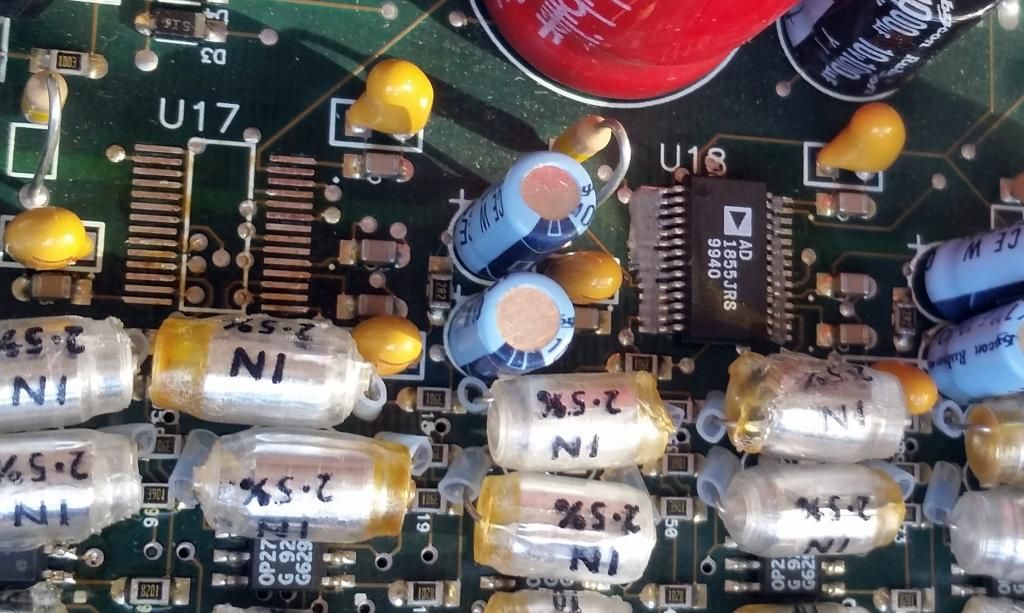
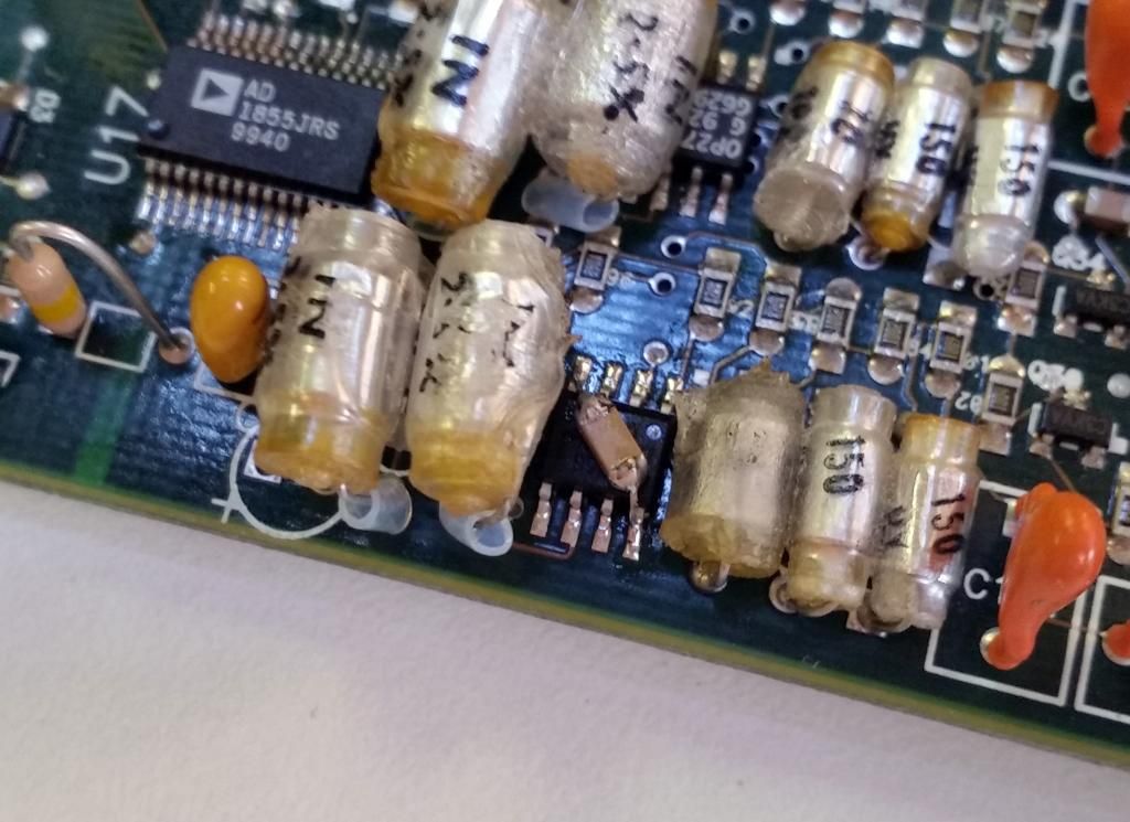
Next step: replace the opamp. This was tough because of the heat-sensitive polystyrene caps covering it. Hot air was out of the question, so cutting the legs carefully and using a curved solder tip did the trick (and even that resulted in some superficial melting of the adjacent polystyerene). I only had a OPA2134 at hand, but that would be fine at least for evaluation.
Result: negative, same problem as before.
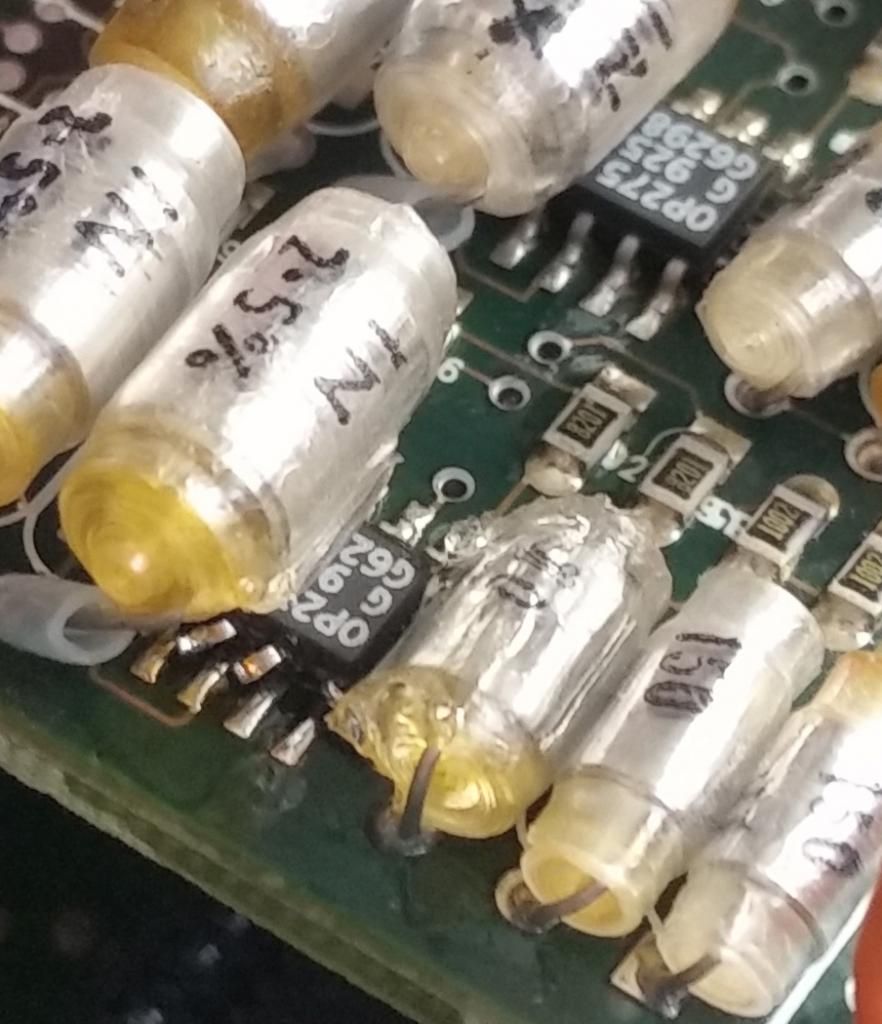
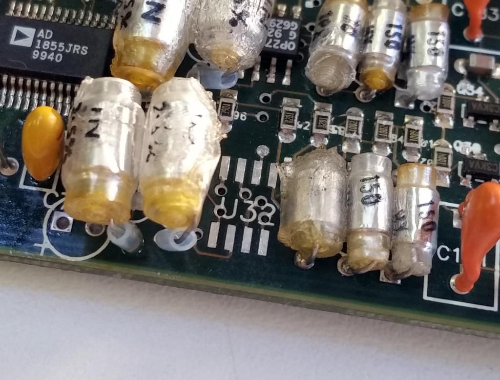
Removing opamp:
I then realized that the opamp decoupling was basically non-existent. The opamps are far away from the regulators, and aside from two 1uF tantalums at the one edge and a 100nF at ONLY ONE rail for every one of the 4-bit muxes, I saw no decoupling whatsoever (the boards are only single-sided; presumably 4-6layer).
My theory then changed that it was probably that the opamps are already marginally unstable with the lack of decoupling, and that age and detereoration of the electrolytics was just enough to push the one opamp into instability: incidentally the right rear channel is the one the furthest away from the regulators. If the opamps were slow old types it might still have been OK, but the OP275 is not slow at all.. this was a bit of an oversight by Meridian IMO.
So, next step: order a bunch of new electrolytics and a replacement OP275 from DigiKey along with a work order. While at it, replace all the elcos on the other boards too. Caps chosen were Nichicon Muse (FW) for the important stuff, and other Nichicon audio grade and Panasonic FC for the rest. No need to go overboard, just as least as good as it was plus maybe a little bit more.
There are four boards in toal, so quite a bit of stripping:
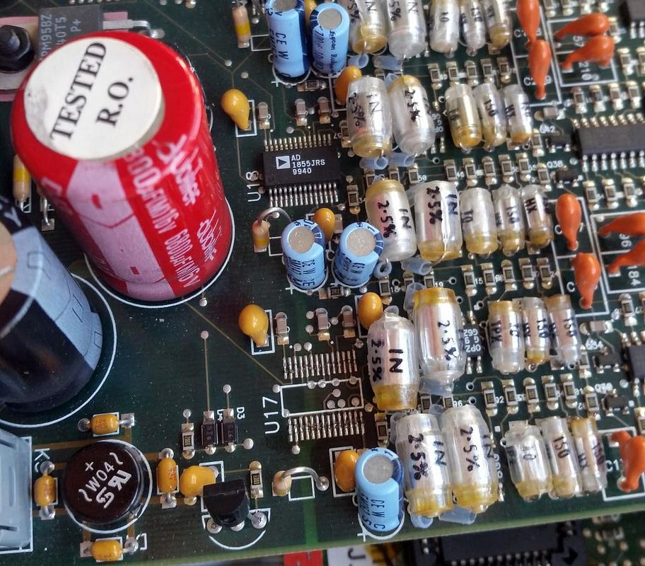
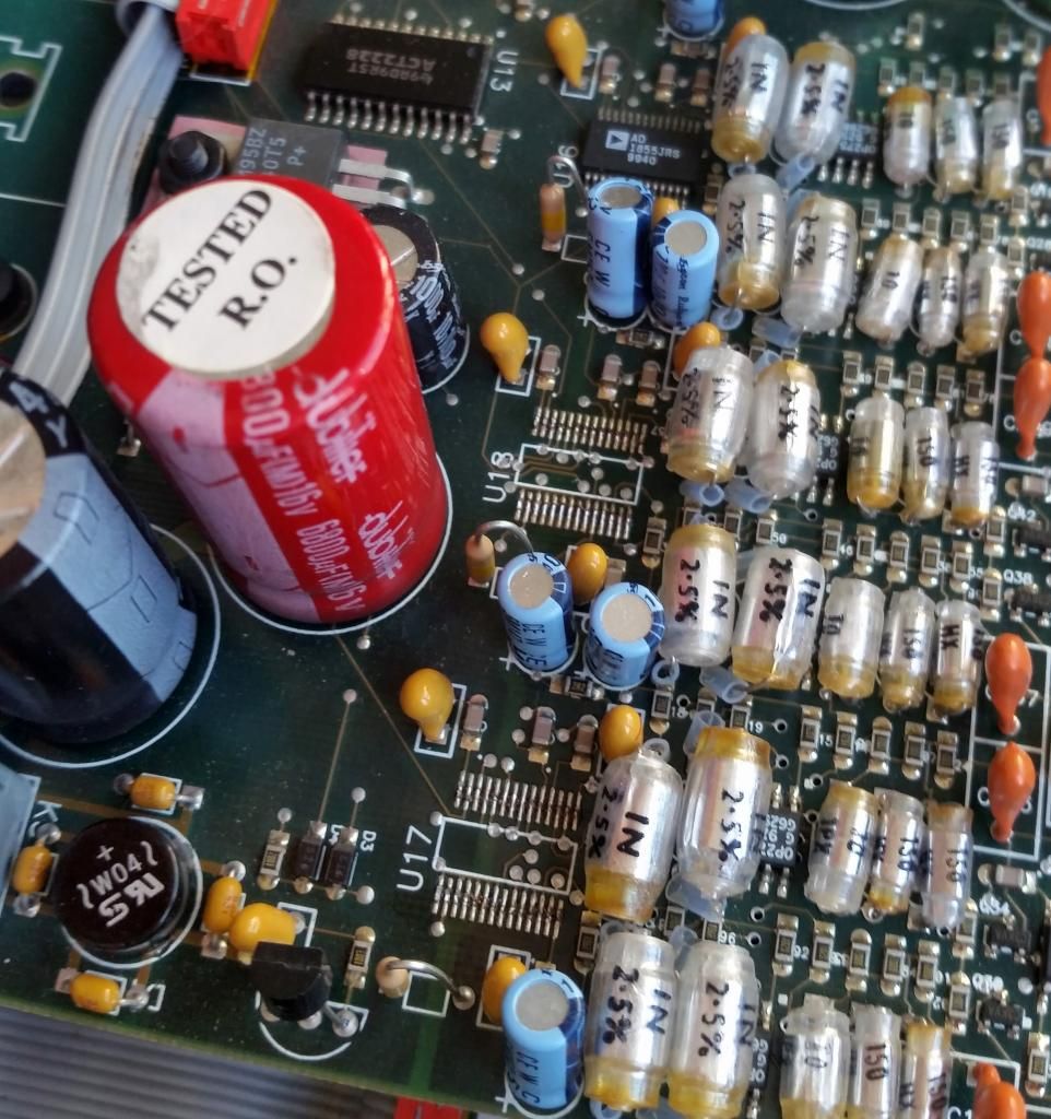
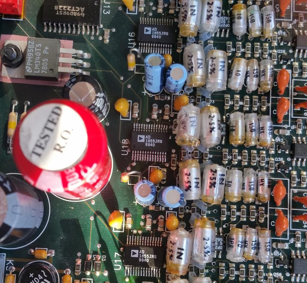
Closeup of DAC board before replacing caps:
Clearly somebody already did some (shoddy) work on the mux of the analog input. Fortunately it a) seems to work and b) I don't use analog in so it's fine.
To decouple the right rear channel opamp, I used a 1uF 25V X7R between the +V and -V pins, carefully soldered with wire wrap. Because of the polystyrene covering, I could not do this for the other channels too, but it's possible with some effort should it ever be necessary.
Pic of new capacitors installed (I even retained the old film layer on top of the tall caps to prevent shorts with the chassis lid):
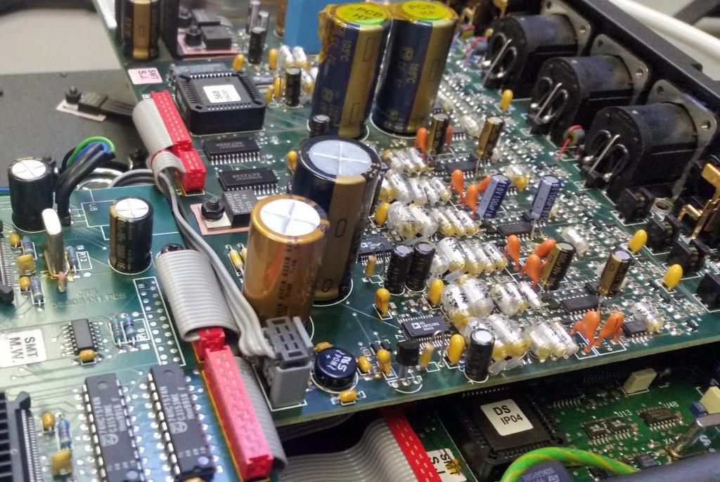
What should be obvious is that I tack-soldered some additional 100uF 10V caps for each channel pair to the +V and -V pins to ground within 3cm of the opamps. This adds some local LF decoupling. If necessary I'll add some 1uF ceramics in parallel but I think this should already do the trick.
Complete pic of the reassembled unit:
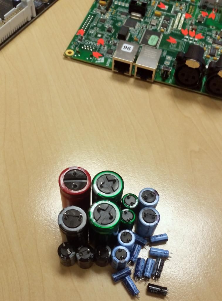
Total tally of removed caps:
Result: It works! All clear, not a noise to be heard. Some of the annoying pops that used to be there when changing modes or sources are also gone now. Perhaps I'll still add some further mods, but I'm rather confident that this on its own shall serve the purpose for the next decade or so")
For anyone interested in the repair & modification process of a Meridian 568: I've taken some pictures during the process, here they are with some comments.
[not sure if this is the right category, mods please assist if necessary]
Recently I bought the 568, only to discover its right rear analog output channel occasionally popped with a large DC offset, followed by approx 12dB attenuation of the actual content and a lot of random noise superimposed on it (no hard feelings to the original owner, who only used it as a 2ch DAC/pre).
After initial sighs (this is after all the SEVENTH processor I bought that had/developed problems!), I opened her up and began probing.
What made the debug process particularly difficult was that the problem only sporadically occurs, often only after many hours of use. By the time the scope probes are going in, the problem has already disappeared again.
First step therefore was to figure out what goes on in the circuit:
We have one stereo AD1855 DAC per set of two channels, hard-configured for 44.1kHz sample rate. This DAC isn't bad at all even by modern standards, except for its digital filter being a tad behind.
After the DAC there is a summing amplifier for the differential DAC voltage outputs, not too different from the datasheet app note but with the difference that it uses a second opamp as virtual ground.
Filter caps are polystyrene; great for the application but I have my doubts whether the large packages and long lead inductance don't negate the advantage. They certainly made debugging a pain. The opamp for the virtual ground driver and summing amp per channel is a dual AD OP275 - not bad at all.
Following this, there is a series DC block with back-to-back tantalum capacitors (not great but oh well), then a crude kind of 4-bit progammable gain amplifier using a 74HCT4052D mux, then a gain stage with a single OPA134, and lastly a simple discrete BJT push-pull amplifier. This is probably to reduce the output impedance and add some current gain.
The front three channels have differential outputs; I didn't check any of that but I guess after the gain amplifier there's another inverting stage.
After the gain stage there's a split in the ground planes, and then the output connectors are coupled with common-mode chokes. I'm not sure whether this was for performance or to meet EMI compliance - this is not often seen on consumer equipment since the EMC qualification level is likely EN 5022 level A; which is easy to pass without additional filters if the design is correct. Such filters often mean there wasn't enough time for debugging: this is often the case in a design rushed to production.
Power supplies for the opamp rails are LM317/337, configured for +-5V from +-10V input, and a standard 7805 for analog power. Pity they used one of the noisiest regulators available for the most sensitive part of the design, and then a fairly clean one for the opamps with >60dB of PSRR.
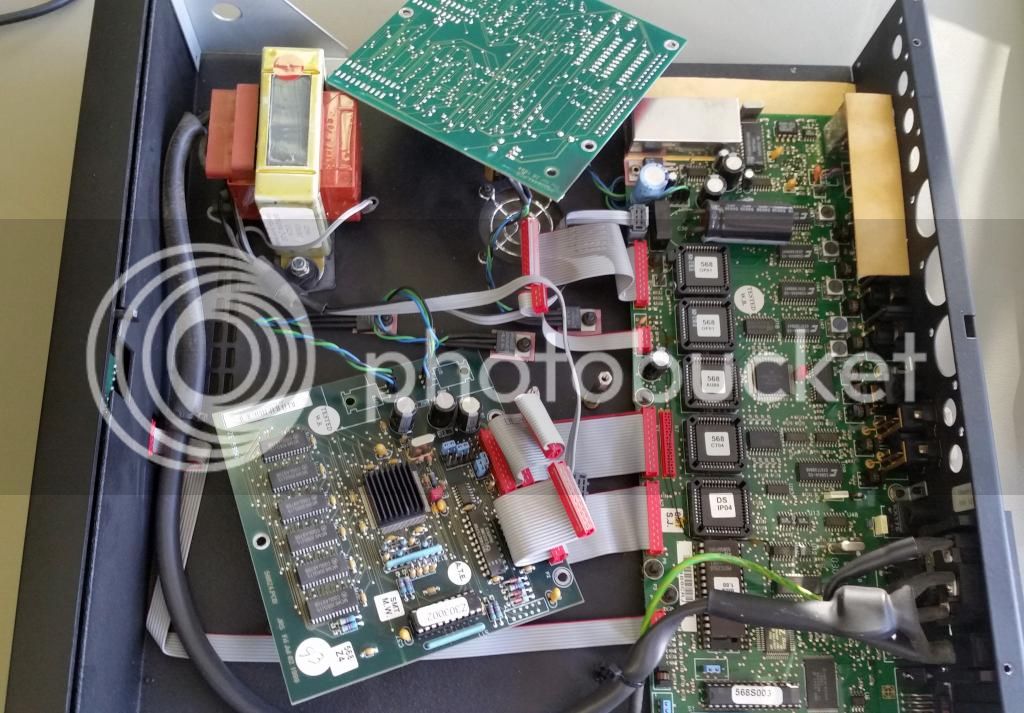
The power at least is cleaner than my old Meridian 565, which was so bad/underspecced I ripped out the transformer and added in custom pre-regulator boards 8 years ago.
Link is at http://www.diyaudio.com/forums/digital-source/101156-my-meridian-565-mod.html
From the 565 pic it should be evident that Meridian re-used a LOT from the 565 design for the 568.
First theory was that the DAC was to blame (partly supported by the fact that this was the problem with the 565 too). Unfortunately, the AD1855 DAC is discontinued: I bought one on eBay, but with SAPO being what it will take weeks to arrive.. if ever.
However, since I do not use side speakers, I kind of have a spare DAC at hand: desolder both the DAC for rears and sides, swop and resolder. This is daunting since one error not only can screw up the DAC, but also possibly tear off a pad and ruining the entire unit for good. However, with the right equipment it's fairly easy:
Removing rear channel DAC:
Removing side channel DAC:
The pads are now full of solder. The solder must be wicked up to have a flat and even surface for the IC to rest on. The footprint at the left is pre-wicked, the one at the right shows the flat surface after wicking. Once again, care is required not to have the pads peel up with the wick:
Put the side channels' DAC IC on the rear channels' footprint, assemble with solder paste, hot air and a fine-tip solder iron:
Rework with flux, hot air and lastly flux remover, and repeat with the swopped IC for the side channels:
Fortunately everything still worked when I plugged it in. However, so did the error after a few hours again! So it seems the fault was not with the DAC.
After some further cursing, I finally managed to reproduce the problem on the bench. On the summing amplifier, there was a huge 1.8MHz oscillation! Since this isn't a multiple of the 44.1kHz sample rate, this does not come from the DAC (from e.g. a busted oversampling filter), and can only be caused by instability in the opamp. The oscillation is what causes the opamp to saturate and the content attenuation, as well as the noise folding back into the audio band.
So, what's causing the oscillation? It's either the opamp itself, the surrounding components, the design, or the layout.
Checked all passive components: fine
Frequency sweep: fine
Layout: can't be since it used to work
Next step: replace the opamp. This was tough because of the heat-sensitive polystyrene caps covering it. Hot air was out of the question, so cutting the legs carefully and using a curved solder tip did the trick (and even that resulted in some superficial melting of the adjacent polystyerene). I only had a OPA2134 at hand, but that would be fine at least for evaluation.
Result: negative, same problem as before.
Removing opamp:
I then realized that the opamp decoupling was basically non-existent. The opamps are far away from the regulators, and aside from two 1uF tantalums at the one edge and a 100nF at ONLY ONE rail for every one of the 4-bit muxes, I saw no decoupling whatsoever (the boards are only single-sided; presumably 4-6layer).
My theory then changed that it was probably that the opamps are already marginally unstable with the lack of decoupling, and that age and detereoration of the electrolytics was just enough to push the one opamp into instability: incidentally the right rear channel is the one the furthest away from the regulators. If the opamps were slow old types it might still have been OK, but the OP275 is not slow at all.. this was a bit of an oversight by Meridian IMO.
So, next step: order a bunch of new electrolytics and a replacement OP275 from DigiKey along with a work order. While at it, replace all the elcos on the other boards too. Caps chosen were Nichicon Muse (FW) for the important stuff, and other Nichicon audio grade and Panasonic FC for the rest. No need to go overboard, just as least as good as it was plus maybe a little bit more.
There are four boards in toal, so quite a bit of stripping:
Closeup of DAC board before replacing caps:
Clearly somebody already did some (shoddy) work on the mux of the analog input. Fortunately it a) seems to work and b) I don't use analog in so it's fine.
To decouple the right rear channel opamp, I used a 1uF 25V X7R between the +V and -V pins, carefully soldered with wire wrap. Because of the polystyrene covering, I could not do this for the other channels too, but it's possible with some effort should it ever be necessary.
Pic of new capacitors installed (I even retained the old film layer on top of the tall caps to prevent shorts with the chassis lid):
What should be obvious is that I tack-soldered some additional 100uF 10V caps for each channel pair to the +V and -V pins to ground within 3cm of the opamps. This adds some local LF decoupling. If necessary I'll add some 1uF ceramics in parallel but I think this should already do the trick.
Complete pic of the reassembled unit:
Total tally of removed caps:
Result: It works! All clear, not a noise to be heard. Some of the annoying pops that used to be there when changing modes or sources are also gone now. Perhaps I'll still add some further mods, but I'm rather confident that this on its own shall serve the purpose for the next decade or so