Ok, so [member=112]DACMan1[/member] convinced me to do simulation of the difference based active crossovers. The result : A flat response curve, but a rate of 6dB/Octave for the calculated channel, even if the filtered one is 12 or 24 dB/Octave. The continuous phase correcting nature of the difference channel, resulted in this slow drop off of 6dB/Octave. This is the price we pay for total phase coherence. It appears this is pretty much unavoidable and if we want even sharper drop off rates on all channels, some compromises need to be made.
Thank you [member=112]DACMan1[/member] for this link into Rod Elliott's adventures down this path... https://sound-au.com/articles/derived-xovers.htm
The classic Linkwitz-Riley, although component sensitive, provides a flat total response, but without phase coherence. In short using it gives you the filtering of an ideal passive crossover, the damping and cone control of an active crossover, the adjustability of an active crossover, but the component sensitivity of a passive crossover.
So all's well if the capacitors are high tolerance, high stability.

There it is. Complete with jumper disconnects, and test points to verify the capacitance. This circuit does require the capacitors to be pretty stable, but not high tolerance. Every filtering capacitor is represented with 3 parallel capacitors. This allows tuning, and adding of capacitance if needed.
A bank or pots allows for the adjustment of the filtering frequency, but they do all need to be set identically to keep the total output flat.
A test point is added to a electrical summing of the 2 output channels. This allows for test equipment, or even just a PC line input to verify the total system frequency response.
Finally a pair of allows for gain adjustment to compensate for drivers with different sensitivities.
Here is a simulation of the systems performance.

Red = LP.
Green = HP.
Blue = LP + HP, providing confirmation of a flat output response.
Notice both HF and LF have 24dB/Octave drop off rates.
Finally, here is the circuit diagram.
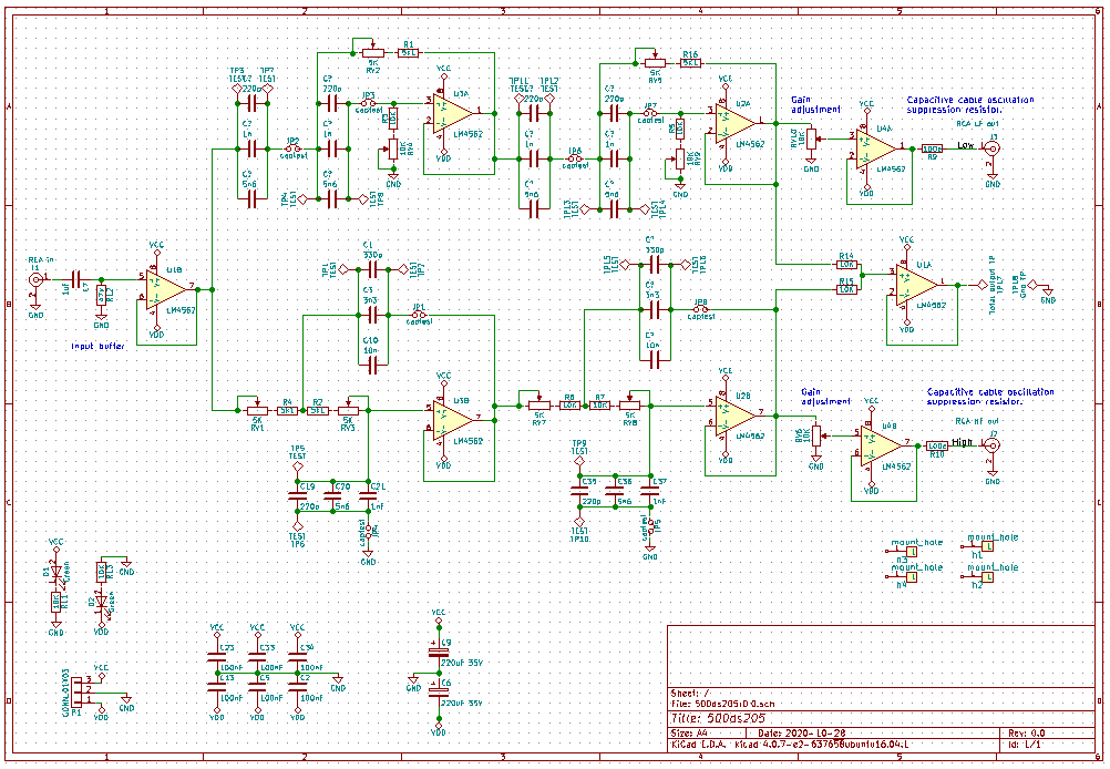
I still need to add 2 resistors to push the system output test point to the same level as the input.
Feedback?
Thank you [member=112]DACMan1[/member] for this link into Rod Elliott's adventures down this path... https://sound-au.com/articles/derived-xovers.htm
The classic Linkwitz-Riley, although component sensitive, provides a flat total response, but without phase coherence. In short using it gives you the filtering of an ideal passive crossover, the damping and cone control of an active crossover, the adjustability of an active crossover, but the component sensitivity of a passive crossover.
So all's well if the capacitors are high tolerance, high stability.
There it is. Complete with jumper disconnects, and test points to verify the capacitance. This circuit does require the capacitors to be pretty stable, but not high tolerance. Every filtering capacitor is represented with 3 parallel capacitors. This allows tuning, and adding of capacitance if needed.
A bank or pots allows for the adjustment of the filtering frequency, but they do all need to be set identically to keep the total output flat.
A test point is added to a electrical summing of the 2 output channels. This allows for test equipment, or even just a PC line input to verify the total system frequency response.
Finally a pair of allows for gain adjustment to compensate for drivers with different sensitivities.
Here is a simulation of the systems performance.
Red = LP.
Green = HP.
Blue = LP + HP, providing confirmation of a flat output response.
Notice both HF and LF have 24dB/Octave drop off rates.
Finally, here is the circuit diagram.
I still need to add 2 resistors to push the system output test point to the same level as the input.
Feedback?