Thought I'd share a little DSP project I've been working on with a colleague for a while now - hardware was done almost 3 years ago but software never got round to being finished until now.
Spoiler alert: most of this project's functionality can be achieved with a MiniDSP.
The idea came when we saw two DIY projects of ours had mutual ground: I wanted a multichannel DSP with stereo S/PDIF input from the head unit to 8ch analog outputs for my car; he wanted a DAC and headphone amplifier with a DSP for crossfade filters, also fed from S/PDIF.
Since we already use much of the technology for our work projects, it was fairly simple to create something with the existing technology. We had the following key requirements:
- Full control of the DSP capabilities without black-box software abstractions, since we also wanted to use the base platform for work research.
- Near-instantaneous startup. That meant no embedded CPU like an ARM module or Raspberry Pi.
- Easy PC control and upload though with native interfaces, so no custom headers with e.g. I2C/SPI/RS232 control
- No unnecessary run-time control or feedback. Once the correct DSP program has been tuned, there's no need for interaction with buttons, displays etc. The only exception to this is preset selction.
- Shared technology without unnecessary duplication. That meant a two-board approach.
- Additional analog and digital I/O's for experimentation and other duties.
- Reasonably simple software migration from previous projects since this is done in free time. That meant eschewing the Sharc DSP for a simpler fixed-point SigmaDSP, which is perfectly fine for the applications we had in mind.
- Simple fixed sample rate of 48kHz 24bit using internal ASRC's
The result was the board below. It contains the following:
- 6layer PCB
- Analog Devices SigmaDSP
- Atmel MCU & 512kB flash with USB interface
- 4pos DIP switch
- Codec with 8ch DAC and 4ch ADC plus buffers
- Isolated electrical S/PDIF input & output
- Toslink input
- status LED's
- expansion port with I2S lines, GPIO's etc.
Picture of the base board is below:
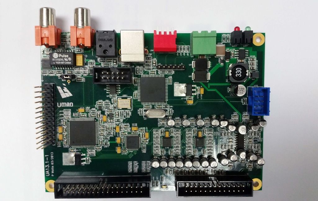
The onboard DAC & ADC is only for experimentation and the signals are only available on a box header. Still, the quality isn't bad (108dB DAC SNR).
The main use-case signal flow is S/PDIF in, which is then asynchronously resampled in the DSP according to a low-jitter local clock domain. The DSP then feeds and clocks the subsequent DAC stages synchronously to this clock. Input sample rates of 32kHz-192kHz are therefore allowed, but it's resampled to 48kHz.
The DSP is managed from a PC via the USB port. The flash connected to the MCU is programmed via USB with up to 16 different DSP projects, which can then be selected with the DIP switch. After programming, the USB connection is not necessary anymore. When power is applied, the MCU boots instantaneously, checks which DIP switch position is selected, reads the appropriate program from the flash and loads it to DSP. GPIO's for resets and mutes etc. are controlled by the MCU too.
The expansion header is for connection to a DAC module. This was one of two units:
a) a high-end stereo DAC with headphone amplifier
b) a medium-quality 8ch DAC with additional protection and control for automotive use.
Since the headphone amp is not my project it's not listed here, but it's also been built and works as expected.
The automotive part is pictured below, shown mounted on top of the base board. It contains:
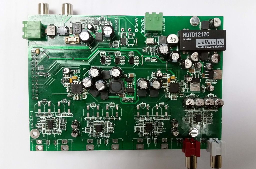
- 2layer PCB
- 2x PCM4104 4ch DAC's
- 8ch analog output
- Reasonably heavy passive (LCLC) filtering & regulated power supplies. Each DAC has its own 5V analog regulator. Opamp power is provided with an isolated switcher module with a subsequent LDO stage to reduce noise, with further LC stages.
- Input power is filtered with both common-mode and differential-mode filtering, a fuse and a TVS for extreme voltage spikes.
- Tightly controlled input power. Included is a main power switch controller, with both over-voltage and undervoltage lockout. The switch powers the circuit as long as the source (battery) voltage is within 11-17VDC, with a hysteresis window. This prevents draining the battery, or malfunctioning, when the battery voltage is outside its expected level. In addition to this, there is an optically isolated remote enable from the car head unit to only enable the board while the head unit is active, once again to conserve power.
- Optically isolated reverse indicator, to fade out the source audio while PDC beeps are playing when in reverse
- Solid-state relays for sequential power-up of attached amplifiers
The project is still ongoing, mostly on the DSP tuning side, but results are exactly as was expected so I'm very happy with the outcome.
Spoiler alert: most of this project's functionality can be achieved with a MiniDSP.
The idea came when we saw two DIY projects of ours had mutual ground: I wanted a multichannel DSP with stereo S/PDIF input from the head unit to 8ch analog outputs for my car; he wanted a DAC and headphone amplifier with a DSP for crossfade filters, also fed from S/PDIF.
Since we already use much of the technology for our work projects, it was fairly simple to create something with the existing technology. We had the following key requirements:
- Full control of the DSP capabilities without black-box software abstractions, since we also wanted to use the base platform for work research.
- Near-instantaneous startup. That meant no embedded CPU like an ARM module or Raspberry Pi.
- Easy PC control and upload though with native interfaces, so no custom headers with e.g. I2C/SPI/RS232 control
- No unnecessary run-time control or feedback. Once the correct DSP program has been tuned, there's no need for interaction with buttons, displays etc. The only exception to this is preset selction.
- Shared technology without unnecessary duplication. That meant a two-board approach.
- Additional analog and digital I/O's for experimentation and other duties.
- Reasonably simple software migration from previous projects since this is done in free time. That meant eschewing the Sharc DSP for a simpler fixed-point SigmaDSP, which is perfectly fine for the applications we had in mind.
- Simple fixed sample rate of 48kHz 24bit using internal ASRC's
The result was the board below. It contains the following:
- 6layer PCB
- Analog Devices SigmaDSP
- Atmel MCU & 512kB flash with USB interface
- 4pos DIP switch
- Codec with 8ch DAC and 4ch ADC plus buffers
- Isolated electrical S/PDIF input & output
- Toslink input
- status LED's
- expansion port with I2S lines, GPIO's etc.
Picture of the base board is below:
The onboard DAC & ADC is only for experimentation and the signals are only available on a box header. Still, the quality isn't bad (108dB DAC SNR).
The main use-case signal flow is S/PDIF in, which is then asynchronously resampled in the DSP according to a low-jitter local clock domain. The DSP then feeds and clocks the subsequent DAC stages synchronously to this clock. Input sample rates of 32kHz-192kHz are therefore allowed, but it's resampled to 48kHz.
The DSP is managed from a PC via the USB port. The flash connected to the MCU is programmed via USB with up to 16 different DSP projects, which can then be selected with the DIP switch. After programming, the USB connection is not necessary anymore. When power is applied, the MCU boots instantaneously, checks which DIP switch position is selected, reads the appropriate program from the flash and loads it to DSP. GPIO's for resets and mutes etc. are controlled by the MCU too.
The expansion header is for connection to a DAC module. This was one of two units:
a) a high-end stereo DAC with headphone amplifier
b) a medium-quality 8ch DAC with additional protection and control for automotive use.
Since the headphone amp is not my project it's not listed here, but it's also been built and works as expected.
The automotive part is pictured below, shown mounted on top of the base board. It contains:
- 2layer PCB
- 2x PCM4104 4ch DAC's
- 8ch analog output
- Reasonably heavy passive (LCLC) filtering & regulated power supplies. Each DAC has its own 5V analog regulator. Opamp power is provided with an isolated switcher module with a subsequent LDO stage to reduce noise, with further LC stages.
- Input power is filtered with both common-mode and differential-mode filtering, a fuse and a TVS for extreme voltage spikes.
- Tightly controlled input power. Included is a main power switch controller, with both over-voltage and undervoltage lockout. The switch powers the circuit as long as the source (battery) voltage is within 11-17VDC, with a hysteresis window. This prevents draining the battery, or malfunctioning, when the battery voltage is outside its expected level. In addition to this, there is an optically isolated remote enable from the car head unit to only enable the board while the head unit is active, once again to conserve power.
- Optically isolated reverse indicator, to fade out the source audio while PDC beeps are playing when in reverse
- Solid-state relays for sequential power-up of attached amplifiers
The project is still ongoing, mostly on the DSP tuning side, but results are exactly as was expected so I'm very happy with the outcome.