So a while ago I purchased a used but immaculate Marantz AV8801 processor from a forumite. Unfortunately, something appeared to have gone awry during shipping as one surround channel cut out sporadically.
I didn't even bother contacting the agents, this is a DIY repair. While I was anyway stripping this thing, I figured some moderate tweaking may also not do any harm.
I focused only on the DAC and summing buffer as it had the biggest room for improvement. The biggest bottleneck in the design is the preamplifier IC to which nothing (sensibly) can be done, so going overboard would anyway serve no purpose. The HDAM modules can do with improvement, but once again space and effort comes into play.
Shoving in additional power supplies and PCB's would have been fun but a) I'm not sure if the cost & effort would be worth the reward and b) the longer the unit stays out of commission the longer I need to listen to TV speakers. So simplicity with stuff from my parts box and a small add-on to a DigiKey order was the solution.
The picture below shows the stock section of the first 8x channels with 4x stereo DAC's (this one comes from the web as it's better resolution than mine). I only worked on the front L&R, Centre, Sub, and surround channels. The rest stayed stock since the difference would not be audible.
So, changes are the following:
- Replace DAC IC's from DAC1795 to PCM1792. These are pin-compatible but have twice the output current, 6dB more dynamic range and twice the price. I replaced them only on the front L&R and Centre&Sub channels.
- Replace summing amplifier opamps from JRC 2068D to my favourite buffer, National LM4562. I kept the I/V conversion opamps at the current NE5532's as they're not too bad there and the green filter caps would risk being damaged from removal. Also, I did not have 6x dual boutique opamps suited for this application in my parts bin and new ones would not be cheap.
- Replace all SMT resistors in the signal parth from the standard cheap 1% thick film type to 0.1% metal film, MELF package. Besides the sonic merits of going to metal film, MELF offers much better thermal coefficients. Increasing the tolerance to 0.1% is useful in these applications where the CMRR is limited by the resistor precision.
- Replace the standard electrolytic power supply capacitors of the DAC's with the lowest-ESR polymer electrolytic available in the same package.
- Replace the critical feedback filter capacitor of the I/V networks with MKP types for centre & surround and polystyrene for L&R.
- Add additional bulk capacitance by augmenting the two main incoming 47uF caps with 470uF polymer electrolytic of the lowest ESR available
Of course, nothing is simple as one had anticipated. I initially thought it would be a simple job by just repeating the same thing for all six channels. This did mean recalculating the output buffer/filter values because of the doubled output current, but I did not envisage that Marantz used a completely different gain profile and filter response for the LRC, sub and surround channels. So I had to reverse-engineer and calculate the existing filters three times in order to calculate the three new sets of filters with identical final gains, frequency & phase response than the old ones. Fortunately I had all the parts at hand and with small exception I could retain the original green film caps although with some swapping around between channels.
Soldering the 0204 MELF resistors onto 0805 footprints also were no joke.. one had to be extremely careful to ensure proper bonding and no shorts between adjacent parts.
So, all is back up and running.
Does it work? Yes.
Are the levels still all matched? Yes, within 1dB from before.
Does it sound better? Dunno but I'd like to think so. Measurements should show some improvement but I didn't bother. Nothing got hot and nothing oscillated so it would be at least as good as it used to be.
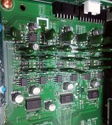
Pic below shows early on, with the first DAC, output opamps, elelctrolytics and a handful of resistors removed
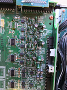
This one shows the DAC's, output opamps and electrolytics replaced along with a few of the resistors with the blue MELF resistors
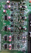
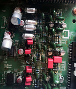
At this point all the resistors are replaced, as well as the MKP & polystyrene caps added
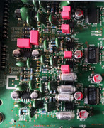
Final pic, with bulk capacitance added; secured with a blob of non-conductive RTV
I didn't even bother contacting the agents, this is a DIY repair. While I was anyway stripping this thing, I figured some moderate tweaking may also not do any harm.
I focused only on the DAC and summing buffer as it had the biggest room for improvement. The biggest bottleneck in the design is the preamplifier IC to which nothing (sensibly) can be done, so going overboard would anyway serve no purpose. The HDAM modules can do with improvement, but once again space and effort comes into play.
Shoving in additional power supplies and PCB's would have been fun but a) I'm not sure if the cost & effort would be worth the reward and b) the longer the unit stays out of commission the longer I need to listen to TV speakers. So simplicity with stuff from my parts box and a small add-on to a DigiKey order was the solution.
The picture below shows the stock section of the first 8x channels with 4x stereo DAC's (this one comes from the web as it's better resolution than mine). I only worked on the front L&R, Centre, Sub, and surround channels. The rest stayed stock since the difference would not be audible.
So, changes are the following:
- Replace DAC IC's from DAC1795 to PCM1792. These are pin-compatible but have twice the output current, 6dB more dynamic range and twice the price. I replaced them only on the front L&R and Centre&Sub channels.
- Replace summing amplifier opamps from JRC 2068D to my favourite buffer, National LM4562. I kept the I/V conversion opamps at the current NE5532's as they're not too bad there and the green filter caps would risk being damaged from removal. Also, I did not have 6x dual boutique opamps suited for this application in my parts bin and new ones would not be cheap.
- Replace all SMT resistors in the signal parth from the standard cheap 1% thick film type to 0.1% metal film, MELF package. Besides the sonic merits of going to metal film, MELF offers much better thermal coefficients. Increasing the tolerance to 0.1% is useful in these applications where the CMRR is limited by the resistor precision.
- Replace the standard electrolytic power supply capacitors of the DAC's with the lowest-ESR polymer electrolytic available in the same package.
- Replace the critical feedback filter capacitor of the I/V networks with MKP types for centre & surround and polystyrene for L&R.
- Add additional bulk capacitance by augmenting the two main incoming 47uF caps with 470uF polymer electrolytic of the lowest ESR available
Of course, nothing is simple as one had anticipated. I initially thought it would be a simple job by just repeating the same thing for all six channels. This did mean recalculating the output buffer/filter values because of the doubled output current, but I did not envisage that Marantz used a completely different gain profile and filter response for the LRC, sub and surround channels. So I had to reverse-engineer and calculate the existing filters three times in order to calculate the three new sets of filters with identical final gains, frequency & phase response than the old ones. Fortunately I had all the parts at hand and with small exception I could retain the original green film caps although with some swapping around between channels.
Soldering the 0204 MELF resistors onto 0805 footprints also were no joke.. one had to be extremely careful to ensure proper bonding and no shorts between adjacent parts.
So, all is back up and running.
Does it work? Yes.
Are the levels still all matched? Yes, within 1dB from before.
Does it sound better? Dunno but I'd like to think so. Measurements should show some improvement but I didn't bother. Nothing got hot and nothing oscillated so it would be at least as good as it used to be.
Pic below shows early on, with the first DAC, output opamps, elelctrolytics and a handful of resistors removed
This one shows the DAC's, output opamps and electrolytics replaced along with a few of the resistors with the blue MELF resistors
At this point all the resistors are replaced, as well as the MKP & polystyrene caps added
Final pic, with bulk capacitance added; secured with a blob of non-conductive RTV