rfq
AVForums Member
Introduction
In recent months, having good headphones (Sennheiser and Shure) it has become increasingly an issue with THD+N especially when listening on the in-built amplifiers of various devices.
I have been using my Technics SU-VZ220 for headphone driving for a number of years, but the noise, as well as the distortion is becoming a problem.
After much procrastination (and after clearing my personal life from moonlighting) I have decided to start the design. This was even more of a motivation after having attempted to listen to Daft Punk - Random Access Memories (which has very low frequency response on some tracks) and giving it up as a bad joke due to distortion.
Purpose
Need an exceptional headphone amplifier, with outstanding specifications, and most importantly, very low THD+N. Additionally, it needs an e-volume (normal log pots are getting harder and harder to get), and facility for a nice, high quality D/A converter, to eliminate the often inferior analogue signal chain on computer motherboards.
Design Details
The first part of the design was to determine a good supply voltage, which of course would dictate the design of the power supply. I estimated that, a power amplifier with 15V DC supply can deliver approximately 12 ~ 13V sinusoid on the output when driven and full ball. With a suitable limit resistor this would be more than enough to drive even the most demanding headphones without blowing them (or the ear-drums of the user).
I then designed the power supply, using a conventional rectifier, two filtering capacitors, and then an unusual bit- regulators for the supply rails. This then provides +15 and -15 volts regulated, with a headroom of at least 1 ampere. Thus the DC voltage going into the amplifier is clean and has no ripple, since the input voltage to the regulators is just over 20V DC. Since I planned to use a high quality op-amp for the input stage, I reckoned it would be a good idea to keep the voltage steady under operating conditions.
Once the power supply was in place, I then proceeded to conceptualize the power amplifier circuit.
What type of output stage do I use here?
Now, the most demanding audiophile will probably want a pure Class A design, where the output device is biased permanently into its linear region, with the least amount of distortion. For tube designs, and others this is perfectly acceptable, however, my experimentation with this for headphones have been met with limited success. The primary findings have been:
I then had a look at consumer grade stuff, and this is where the rail-to-rail op-amp dominates. For consumers this is an acceptable approach, but it suffers from noise, and in addition, runs out of power with demanding use, leading to clipping and horrible distortion with deep bass.
Therefore my choice is confined to the Class AB output stage, which then affords me the following advantages
I also knew that, with careful, painstaking design I would be able to bias the transistors so that at very small signal conditions, the stage is basically Class A (with a consequent acceptable power dissipation). This would greatly eliminate the crossover distortion problem, and one could possibly get rid of it altogether. Cheap, class B designs, ones that typically produce audible hiss (and have output capacitors) are generally Class B. The audible hiss is due to the negative feedback.
Then, taking into consideration we would sink typically an absolute maximum of about 1 watt into a 32 ohm load (and considerably less with different headphones) I chose the complementary pair.
The BD139 and BD140 make ideal transistors for this amplifier. Especially when you look at the H-parameters, they are virtually identical for both the NPN and PNP devices.
http://www.st.com/web/en/resource/technical/document/datasheet/CD00001225.pdf
Key specs of this transistor are 1.5A max collector current (more than adequate), and power dissipation is excellent at 12.5W which gives us a margin of 10 times. These devices are also cheap.
Typical headphone impedance is 32 ohms. Include a 100 ohm limiting resistor in series, and it gives a total of 132 ohms nominal.
So we begin with the Class AB design, as shown here, with two emitter degeneration resistors (RE1 & RE2)
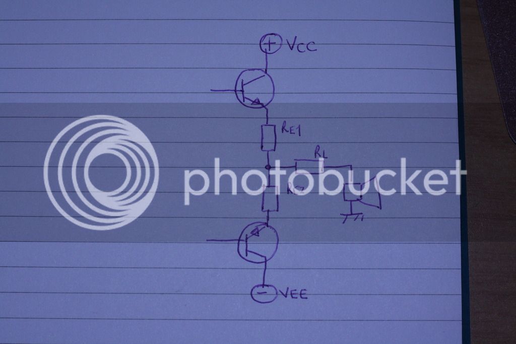
Since the power output is maybe 1 watt maximum, we can choose RE1 = RE2 = 27 ohms.
Now to prove that 27 ohms is optimal, would involve mind-numbing pages of maths and I am sure by then I would have lost the readership, suffice to say the calculations were done and are in my book if anyone needs to inspect them. The formulae are standardized and can be found in this book
https://books.google.co.za/books?id=RcodQm6LaVEC&redir_esc=y Page 540 - 546
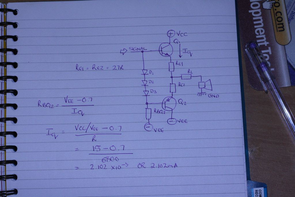
The next aspect, which is critical to the design, is the biasing. Both transistors need to be biased in such a way that the quiescent current is not excessive, and at small signal, behaves like Class A i.e. one of the transistors predominantly conducting. To bias the transistors, we will use the Widlar current source, which is a set of diodes between the bases of the transistors, with the signal applied at some point. These diodes act as current mirrors, biasing the transistors optimally. Since I wish to use an op-amp (which has a single-ended output) a slight deviation is in order. Also because I know I can pull the imbalance to zero with negative feedback, I design the current source with three diodes and only one resistor as shown.
RBQ2 sets the quiescent current, and choosing a value of 6k8, gives around 2.1mA which is great. So we don't have anything that will potentially be a heater. Also, the low quiescent current should be more than adequate for the op-amp to handle.
Now, for the sake of completeness, we will draw our complete power output stage in Class AB.
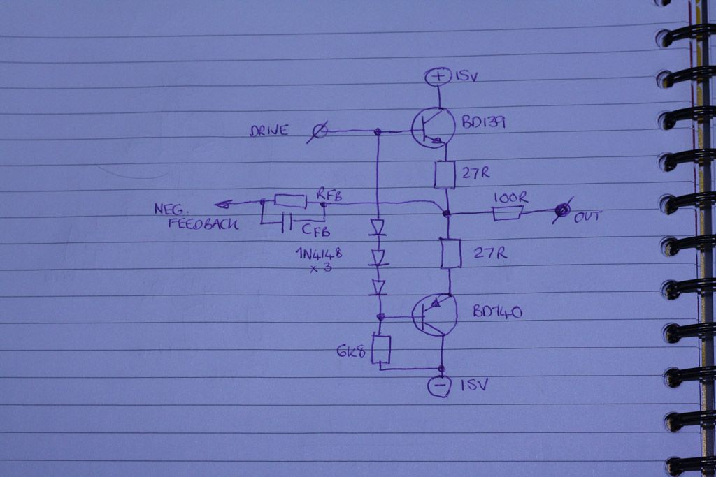
Now, for the moment, the negative feedback path consisting of RFB and CFB will be left as unknowns, we will calculate them in the next part.
In recent months, having good headphones (Sennheiser and Shure) it has become increasingly an issue with THD+N especially when listening on the in-built amplifiers of various devices.
I have been using my Technics SU-VZ220 for headphone driving for a number of years, but the noise, as well as the distortion is becoming a problem.
After much procrastination (and after clearing my personal life from moonlighting) I have decided to start the design. This was even more of a motivation after having attempted to listen to Daft Punk - Random Access Memories (which has very low frequency response on some tracks) and giving it up as a bad joke due to distortion.
Purpose
Need an exceptional headphone amplifier, with outstanding specifications, and most importantly, very low THD+N. Additionally, it needs an e-volume (normal log pots are getting harder and harder to get), and facility for a nice, high quality D/A converter, to eliminate the often inferior analogue signal chain on computer motherboards.
Design Details
The first part of the design was to determine a good supply voltage, which of course would dictate the design of the power supply. I estimated that, a power amplifier with 15V DC supply can deliver approximately 12 ~ 13V sinusoid on the output when driven and full ball. With a suitable limit resistor this would be more than enough to drive even the most demanding headphones without blowing them (or the ear-drums of the user).
I then designed the power supply, using a conventional rectifier, two filtering capacitors, and then an unusual bit- regulators for the supply rails. This then provides +15 and -15 volts regulated, with a headroom of at least 1 ampere. Thus the DC voltage going into the amplifier is clean and has no ripple, since the input voltage to the regulators is just over 20V DC. Since I planned to use a high quality op-amp for the input stage, I reckoned it would be a good idea to keep the voltage steady under operating conditions.
Once the power supply was in place, I then proceeded to conceptualize the power amplifier circuit.
What type of output stage do I use here?
Now, the most demanding audiophile will probably want a pure Class A design, where the output device is biased permanently into its linear region, with the least amount of distortion. For tube designs, and others this is perfectly acceptable, however, my experimentation with this for headphones have been met with limited success. The primary findings have been:
- low output power
- excessive heat
- the headphone has to be coupled to the output stage via a capacitor, this does have an effect on the sound
I then had a look at consumer grade stuff, and this is where the rail-to-rail op-amp dominates. For consumers this is an acceptable approach, but it suffers from noise, and in addition, runs out of power with demanding use, leading to clipping and horrible distortion with deep bass.
Therefore my choice is confined to the Class AB output stage, which then affords me the following advantages
- direct load coupling
- ability to match the output devices closely
- no heating and no wasteful excessive current flow
I also knew that, with careful, painstaking design I would be able to bias the transistors so that at very small signal conditions, the stage is basically Class A (with a consequent acceptable power dissipation). This would greatly eliminate the crossover distortion problem, and one could possibly get rid of it altogether. Cheap, class B designs, ones that typically produce audible hiss (and have output capacitors) are generally Class B. The audible hiss is due to the negative feedback.
Then, taking into consideration we would sink typically an absolute maximum of about 1 watt into a 32 ohm load (and considerably less with different headphones) I chose the complementary pair.
The BD139 and BD140 make ideal transistors for this amplifier. Especially when you look at the H-parameters, they are virtually identical for both the NPN and PNP devices.
http://www.st.com/web/en/resource/technical/document/datasheet/CD00001225.pdf
Key specs of this transistor are 1.5A max collector current (more than adequate), and power dissipation is excellent at 12.5W which gives us a margin of 10 times. These devices are also cheap.
Typical headphone impedance is 32 ohms. Include a 100 ohm limiting resistor in series, and it gives a total of 132 ohms nominal.
So we begin with the Class AB design, as shown here, with two emitter degeneration resistors (RE1 & RE2)
Since the power output is maybe 1 watt maximum, we can choose RE1 = RE2 = 27 ohms.
Now to prove that 27 ohms is optimal, would involve mind-numbing pages of maths and I am sure by then I would have lost the readership, suffice to say the calculations were done and are in my book if anyone needs to inspect them. The formulae are standardized and can be found in this book
https://books.google.co.za/books?id=RcodQm6LaVEC&redir_esc=y Page 540 - 546
The next aspect, which is critical to the design, is the biasing. Both transistors need to be biased in such a way that the quiescent current is not excessive, and at small signal, behaves like Class A i.e. one of the transistors predominantly conducting. To bias the transistors, we will use the Widlar current source, which is a set of diodes between the bases of the transistors, with the signal applied at some point. These diodes act as current mirrors, biasing the transistors optimally. Since I wish to use an op-amp (which has a single-ended output) a slight deviation is in order. Also because I know I can pull the imbalance to zero with negative feedback, I design the current source with three diodes and only one resistor as shown.
RBQ2 sets the quiescent current, and choosing a value of 6k8, gives around 2.1mA which is great. So we don't have anything that will potentially be a heater. Also, the low quiescent current should be more than adequate for the op-amp to handle.
Now, for the sake of completeness, we will draw our complete power output stage in Class AB.
Now, for the moment, the negative feedback path consisting of RFB and CFB will be left as unknowns, we will calculate them in the next part.