Hi All
I have had request to look into the Leak TL25+ output transformer design, and clone or redesign it. (I am not trying to reinvent the wheel, or improve the work of the illustrious Leak Company, but only to fill in the gaps of information, where information is wanting)
Here is the schematic:

From the voltages noted on the schematic, I can calculate the expected current running through each output tube, and by inference through each section of the OPT.
So 30V/440ohms=68mA DC
There is more info on this page http://www.44bx.com/leak/transformers.html
Here I see the transformer is called the 3925 and the primary impedance is 7000 ohms with UL taps at 49%. The DC resistance from anode to anode is 102 ohms.
If I punch all this data into OPT design assistant I get this design:
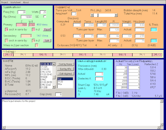
Completely do-able on a 60mm stack of EI96 laminations.
Now the formula for power and primary impedance is
(Anode-to-Cathode-Voltage)/Power-Output
Thus from the schematic
420 X 420 / 25 = 7056
which is spot on.
Now the request is to design a beefier OPT to handle the higher currents of KT88's and 6550. These tubes would idle 100mA DC. Another suggestion was made to design for 35 watts output (to have a bit of headroom).
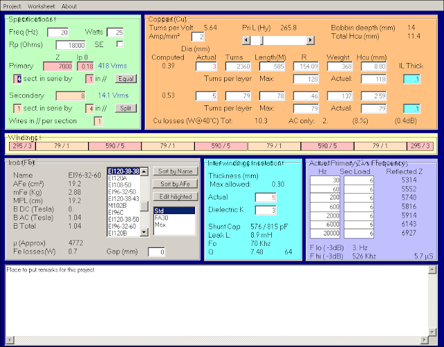
Let us explore this. Jacking up the current, does not need more iron. The thickness of the copper and the resultant heat is the issue as can be see from this screenshot. I need to keep copper losses not more than 10%. This will only happen when the current gets to 180mA - well above the KT88 margins.
To get 35 watt though the trafo gets bigger:
Now we need to use EI114 laminations:

You need a voltage of sqr-root(7000 x 35) = 495 volts to realise this. It is not so difficult to do this. One can pull the tube rectifier and fit a two diodes and a resistor to get the voltages up. You need to check you filter caps max voltage though.
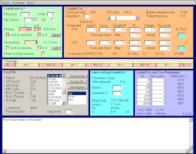
Otherwise to get 35 watts out of this same amp with 420V on the plates, you'll need a 5000 primary impedance which leads to this:
But now the trick is to design an OPT that can run on EL34's and KT88! To put taps on the Anode and Screen grid taps is impractical. Rather tap the secondary:

This turns out to be a 16 ohm tap! Now it is unwise to tap a secondary in a parallel arrangement. So if we change our secondary design to a 2 sections in series and both in parallel, we have full secondary layers connected in 5000 and 7000 ohm pri imp configurations.
We have gone the full circle and are back to a OPT with a 16 ohm tap! The final design I'll post next.
I have had request to look into the Leak TL25+ output transformer design, and clone or redesign it. (I am not trying to reinvent the wheel, or improve the work of the illustrious Leak Company, but only to fill in the gaps of information, where information is wanting)
Here is the schematic:
From the voltages noted on the schematic, I can calculate the expected current running through each output tube, and by inference through each section of the OPT.
So 30V/440ohms=68mA DC
There is more info on this page http://www.44bx.com/leak/transformers.html
Here I see the transformer is called the 3925 and the primary impedance is 7000 ohms with UL taps at 49%. The DC resistance from anode to anode is 102 ohms.
If I punch all this data into OPT design assistant I get this design:
Completely do-able on a 60mm stack of EI96 laminations.
Now the formula for power and primary impedance is
(Anode-to-Cathode-Voltage)/Power-Output
Thus from the schematic
420 X 420 / 25 = 7056
which is spot on.
Now the request is to design a beefier OPT to handle the higher currents of KT88's and 6550. These tubes would idle 100mA DC. Another suggestion was made to design for 35 watts output (to have a bit of headroom).
Let us explore this. Jacking up the current, does not need more iron. The thickness of the copper and the resultant heat is the issue as can be see from this screenshot. I need to keep copper losses not more than 10%. This will only happen when the current gets to 180mA - well above the KT88 margins.
To get 35 watt though the trafo gets bigger:
Now we need to use EI114 laminations:
You need a voltage of sqr-root(7000 x 35) = 495 volts to realise this. It is not so difficult to do this. One can pull the tube rectifier and fit a two diodes and a resistor to get the voltages up. You need to check you filter caps max voltage though.
Otherwise to get 35 watts out of this same amp with 420V on the plates, you'll need a 5000 primary impedance which leads to this:
But now the trick is to design an OPT that can run on EL34's and KT88! To put taps on the Anode and Screen grid taps is impractical. Rather tap the secondary:
This turns out to be a 16 ohm tap! Now it is unwise to tap a secondary in a parallel arrangement. So if we change our secondary design to a 2 sections in series and both in parallel, we have full secondary layers connected in 5000 and 7000 ohm pri imp configurations.
We have gone the full circle and are back to a OPT with a 16 ohm tap! The final design I'll post next.