I had this project going for a while and have sold some crossovers. Here is a new revision for comments. Now using new PCB services and SMD parts.
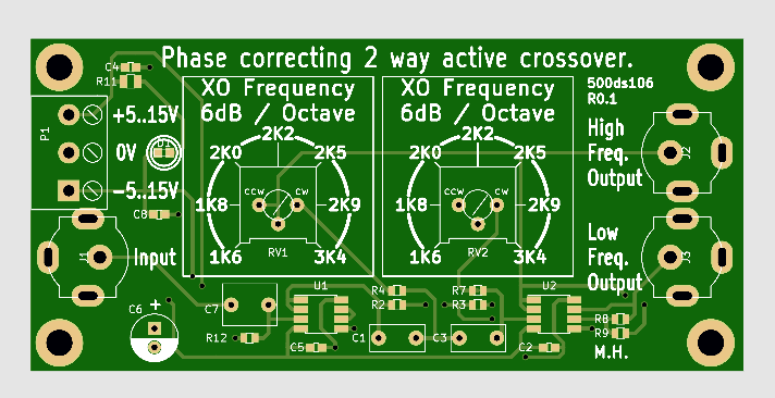
The input and outputs are now via RCA plugs.
Adjustable crossover frequency.
A new low price for this initial run of 10, R120 per active crossover, assembled, excluding shipping.
The basic benefits of this circuit are as follows.
1. Traditional Crossovers rely on filter components which are subject to high voltages, and currents, while having to remain linear and stable. If a component drifts slightly, it's not just the crossover frequency that shifts, but the total system response is altered as one driver reduces or increases its output at the crossover point while the other does not. Therefore it is vital that the low and high frequency paths have high tolerance, high temperature stability, low drift, high voltage parts. This is a tall order.
2. At the crossover frequency, while one driver is phase shifted in one direction, the other driver is shifted in exactly the opposite direction. The result is that the output signal is partially canceled, complicating passive crossovers.
3. Amplifiers nowadays have spectacular damping factor figures with output impedances in the milliohms. This results in low distortion because of tight driver motion control. All this is lost at crossover where we suddenly introduce an impedance measured in ohms. resulting in poos control and ample ringing.
Active crossovers have a amplifier per driver. Delivering optimal damping factor throughout the audio range.
Active crossovers filter at low level, reducing much of the restrictive requirements placed on the filter components.
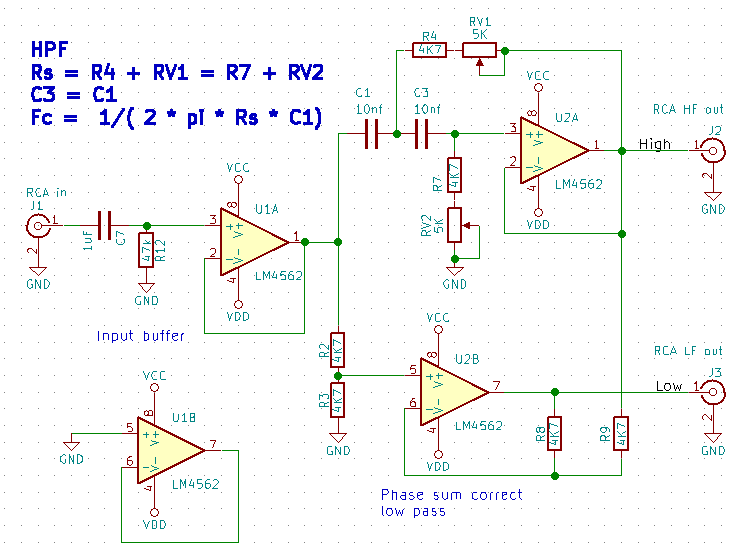
This specific active crossover design uses a special technique to ensure the total system response remains perfectly flat. If the filtering components drift, the only thing that drifts is the crossover frequency, not the system response. This is achieved by only filtering one path, and using a difference circuit to determine the other path. This simple technique compensates for phase cancellation, initial component tolerance and drift.


 online picture hosting
If anyone is interested in a pcb let me know.
Additionally, any input regarding the design would be greatly appreciated.
Murray.
The input and outputs are now via RCA plugs.
Adjustable crossover frequency.
A new low price for this initial run of 10, R120 per active crossover, assembled, excluding shipping.
The basic benefits of this circuit are as follows.
1. Traditional Crossovers rely on filter components which are subject to high voltages, and currents, while having to remain linear and stable. If a component drifts slightly, it's not just the crossover frequency that shifts, but the total system response is altered as one driver reduces or increases its output at the crossover point while the other does not. Therefore it is vital that the low and high frequency paths have high tolerance, high temperature stability, low drift, high voltage parts. This is a tall order.
2. At the crossover frequency, while one driver is phase shifted in one direction, the other driver is shifted in exactly the opposite direction. The result is that the output signal is partially canceled, complicating passive crossovers.
3. Amplifiers nowadays have spectacular damping factor figures with output impedances in the milliohms. This results in low distortion because of tight driver motion control. All this is lost at crossover where we suddenly introduce an impedance measured in ohms. resulting in poos control and ample ringing.
Active crossovers have a amplifier per driver. Delivering optimal damping factor throughout the audio range.
Active crossovers filter at low level, reducing much of the restrictive requirements placed on the filter components.
This specific active crossover design uses a special technique to ensure the total system response remains perfectly flat. If the filtering components drift, the only thing that drifts is the crossover frequency, not the system response. This is achieved by only filtering one path, and using a difference circuit to determine the other path. This simple technique compensates for phase cancellation, initial component tolerance and drift.
online picture hostingIf anyone is interested in a pcb let me know.
Additionally, any input regarding the design would be greatly appreciated.
Murray.