For a change, a class-D repair/renovation instead of construction, and for a change a piecewise thread instead of a full one when done.
Some of you might remember Seanjammy's unfortunate luck with his UCD700HG amp's power supply malfunction and the speculation on the half-priced sales thread about whether it was a bargain should it be:
a) just a fuse
b) a major repair effort or
c) a new power supply with landed cost after shipping & taxes >R5k
Pic of the opened amp from the ad here:
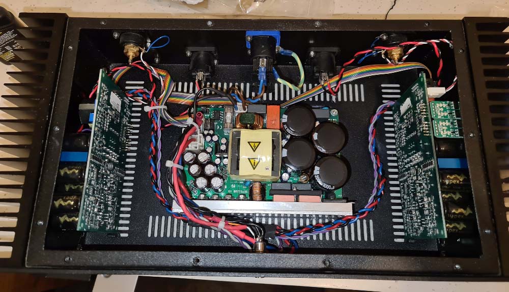
Spoiler alert, the problem was not a). Since the bulk of the components are tiny SMT devices with little or no markings, it was a harrowing repair attempt. Some traces disintegrated and had to be replaced with wires. Also, because of the massive power, just doing a few repairs and flipping the power switch is a BAD idea. There's serious shrapnel risk involved, as was evident when I thought everything broken was replaced. Thankfully I placed a plastic box over it; habit from working with these things in the old days. The error turned out to be a via that had disintegrated from the power, so the signal did not cross the board from top to bottom. Tough to measure these things.
It took meticulous attention to measuring every single semiconductor, sometimes requiring temporary removal, as well as resistors. From the sheer power some resistors failed in strange ways: usually they fail as open-circuits, but I found two that failed as random resistance values, e.g. a 220R that become something around 200k. In total besides checking every part I replaced about 10 resistors, one capacitor, five diodes and eight transistors.
I was on the verge of giving up since one burnt resistor I had no idea of value or function, when I remembered I still had some Hypex technical contacts who were surprisingly helpful in tracking down the resistor value.
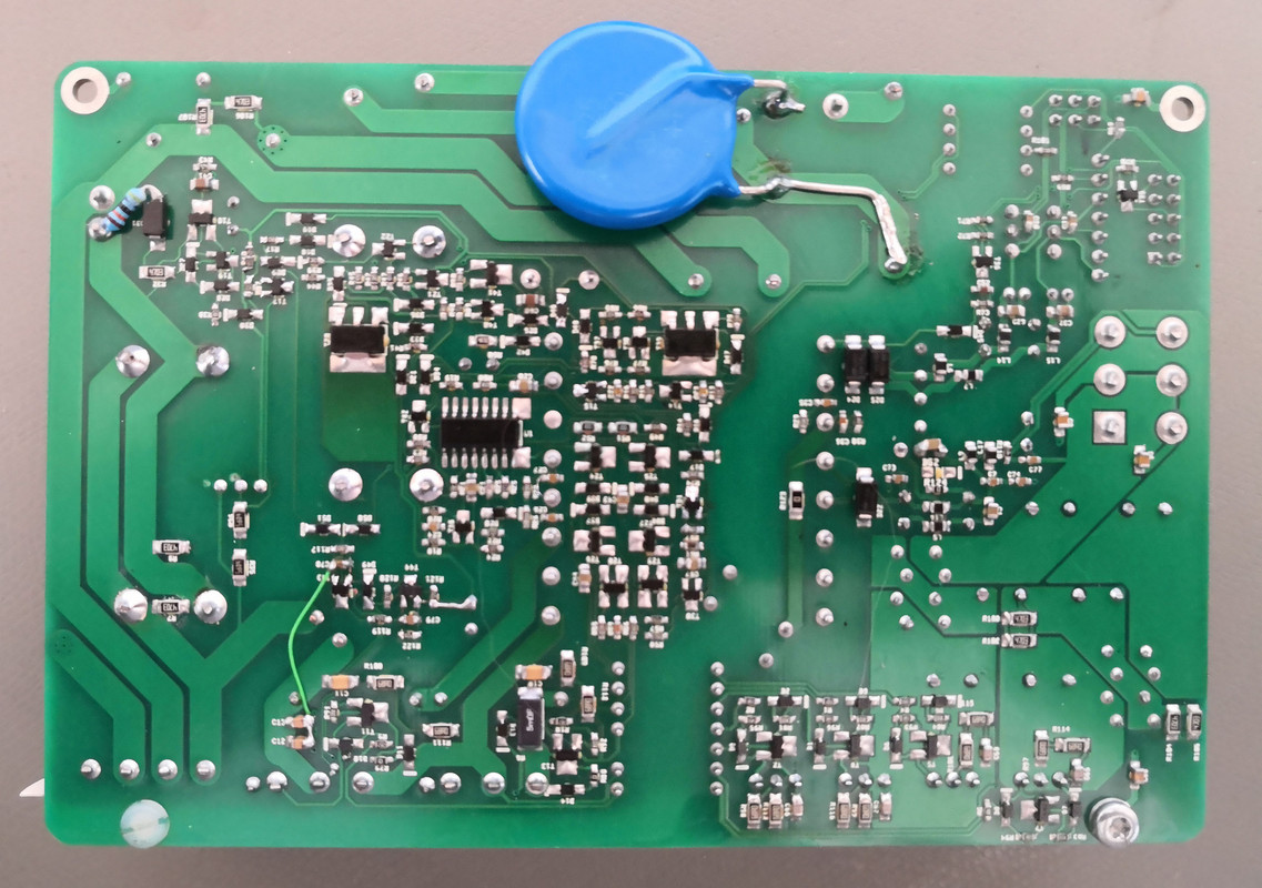
Here is a picture of the restored power supply (the through-hole resistor is actually a stock item and not a repair). I also added a massive MOV for protection since the PSU does not have any input protection circuitry.
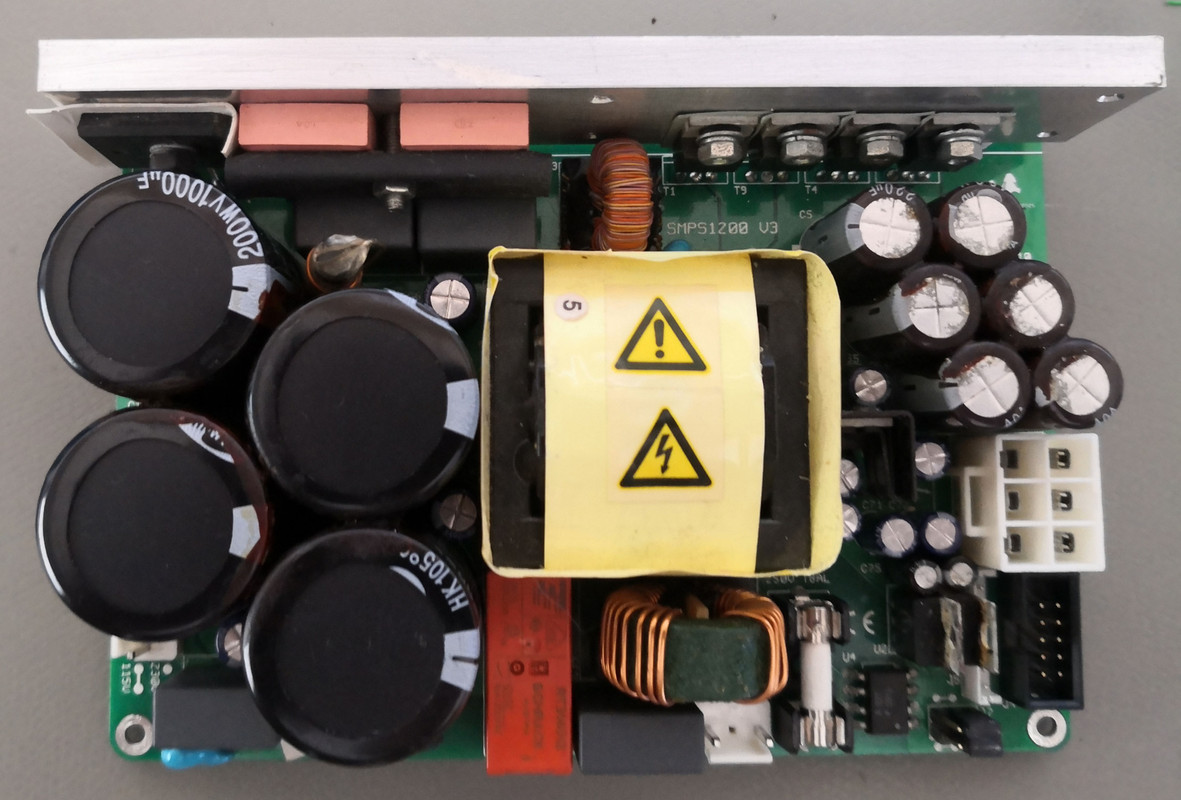
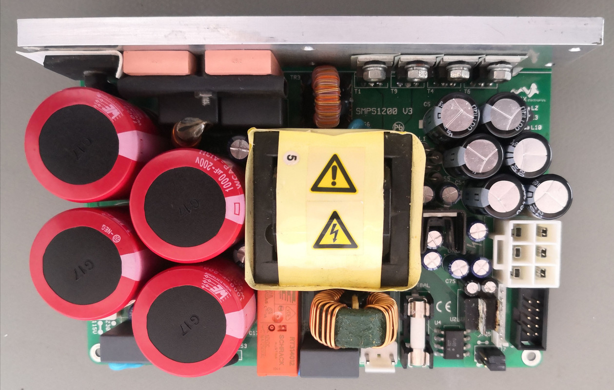
While I was at it, I decided to also recap the power supply: I do not advocate at all blindly recapping in most applications EXCEPT where serious heat&age, high switching ripple current or short-circuit cap discharge was involved. This supply had experienced the latter two. The new caps were not cheap, but much less than importing a new power supply. The new caps are also significantly better than the old ones, with much higher ripple handling capability and rated lifespan. The caps involved are the four big input caps as well as the six output caps. The other smaller electrolytics serve no critical purpose and were left in peace. Below are some before and after pics.
BEFORE:
AFTER:
So what's next? It's a bit of a gamble as I just realized I haven't tested the amp modules yet, but I'm quite sure they are fine.
While anyway stripping most of the amp I can just as well go further and I did find a few areas that can do with improvement:
1) Add a proper standby circuit. Sean added a front-panel power switch that is just a series mains switch with LED illumination. However, the power supply itself has a standby mode and I want 12VDC triggers on all my equipment. So, mount a small PCB at the back of the amp with a 3.5mm trigger socket controlling the amplifier standby. Sadly, for reasons I REALLY do not understand, Hypex made the standby mode to be Active High. This means it requires a positive voltage to turn the power supply OFF. Most power supplies I've encountered are Active Low, meaning there's a self-powered pin that, when grounded, will turn the PSU off. In this case then it means a separate power source is required. Fortunately since I'm anyway having a trigger PCB made, I can just as well add the smallest little 1W AC/DC power supply with sole purpose to only produce enough current to turn on an optocoupler. The power supply was chosen since it has negligible standby current of <75mW and complies to class-B emissions ratings without external filters. Since insulted 3.5mm sockets with thread that can mount the board by itself are scarce as hen's teeth, I added two right-angle threaded parts to firmly mount the board to the back panel. Parts are here and PCB is shipped so it should be done soon. PCB drawing below.
2) Change RCA's to XLR. Contentious and I know SE can sound just as good or better than differential, but there is merit. Firstly this amp was built with pro audio considerations i.e. Neutrik Speakon and Powercon speaker and power terminals. XLR just fits the mould better and I've had it with chasing down ground loops in more complex systems. Furthermore, the Hypex amplifier modules themselves have differential inputs so why not expose that. I briefly thought about retaining the RCA's but that would have required adding switches to short out pin3 to pin1 which just is too much work and can always be added in the future since the chassis conveniently has one more set of blanking plates for Neutrik plugs to avoid any drilling (except for the shorting switches). Parts are with me but all mechanical work to be done at the same time while anyway stripping out everything.
3) Replace the power capacitors on the amplifier modules. Same argument as before: switching amps live a hard life and on diyaudio there were reports that of these modules suffering from capacitor failure in later life. No idea of the capacitor pedigree used as they are Hypex-rebranded, but (despite the branding) it's unlikely to be the very best purely because of cost. The replacement caps are once again the lowest ESR, highest ripple current and longest life available in the same footprint. While at it, bypass the caps with Wima MKP10 polypropylene. Parts to be ordered soon.
4) Re-route suboptimal wiring and replace some wiring. Power and signal wiring are spaced too closely and needs careful rerouting for best performance. Power and speaker cables are too thin IMO and will be replaced, and interconnect wire seems like CAT5. Will replace all that with whatever I have available.
In total this is/was not exactly cheap, but worth it. Total time if nothing goes wrong should be about 20h and materials estimated at R1500ish. However, I believe this is worthwhile. Not only will it reset the condition to like when it was new, overall longevity compared to just replacing modules is extended, performance is likely improved and functionality extended by the trigger input addition.
Updates to come as PCB, parts and time are available.
Some of you might remember Seanjammy's unfortunate luck with his UCD700HG amp's power supply malfunction and the speculation on the half-priced sales thread about whether it was a bargain should it be:
a) just a fuse
b) a major repair effort or
c) a new power supply with landed cost after shipping & taxes >R5k
Pic of the opened amp from the ad here:
Spoiler alert, the problem was not a). Since the bulk of the components are tiny SMT devices with little or no markings, it was a harrowing repair attempt. Some traces disintegrated and had to be replaced with wires. Also, because of the massive power, just doing a few repairs and flipping the power switch is a BAD idea. There's serious shrapnel risk involved, as was evident when I thought everything broken was replaced. Thankfully I placed a plastic box over it; habit from working with these things in the old days. The error turned out to be a via that had disintegrated from the power, so the signal did not cross the board from top to bottom. Tough to measure these things.
It took meticulous attention to measuring every single semiconductor, sometimes requiring temporary removal, as well as resistors. From the sheer power some resistors failed in strange ways: usually they fail as open-circuits, but I found two that failed as random resistance values, e.g. a 220R that become something around 200k. In total besides checking every part I replaced about 10 resistors, one capacitor, five diodes and eight transistors.
I was on the verge of giving up since one burnt resistor I had no idea of value or function, when I remembered I still had some Hypex technical contacts who were surprisingly helpful in tracking down the resistor value.
Here is a picture of the restored power supply (the through-hole resistor is actually a stock item and not a repair). I also added a massive MOV for protection since the PSU does not have any input protection circuitry.
While I was at it, I decided to also recap the power supply: I do not advocate at all blindly recapping in most applications EXCEPT where serious heat&age, high switching ripple current or short-circuit cap discharge was involved. This supply had experienced the latter two. The new caps were not cheap, but much less than importing a new power supply. The new caps are also significantly better than the old ones, with much higher ripple handling capability and rated lifespan. The caps involved are the four big input caps as well as the six output caps. The other smaller electrolytics serve no critical purpose and were left in peace. Below are some before and after pics.
BEFORE:
AFTER:
So what's next? It's a bit of a gamble as I just realized I haven't tested the amp modules yet, but I'm quite sure they are fine.
While anyway stripping most of the amp I can just as well go further and I did find a few areas that can do with improvement:
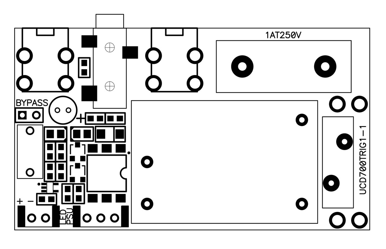
1) Add a proper standby circuit. Sean added a front-panel power switch that is just a series mains switch with LED illumination. However, the power supply itself has a standby mode and I want 12VDC triggers on all my equipment. So, mount a small PCB at the back of the amp with a 3.5mm trigger socket controlling the amplifier standby. Sadly, for reasons I REALLY do not understand, Hypex made the standby mode to be Active High. This means it requires a positive voltage to turn the power supply OFF. Most power supplies I've encountered are Active Low, meaning there's a self-powered pin that, when grounded, will turn the PSU off. In this case then it means a separate power source is required. Fortunately since I'm anyway having a trigger PCB made, I can just as well add the smallest little 1W AC/DC power supply with sole purpose to only produce enough current to turn on an optocoupler. The power supply was chosen since it has negligible standby current of <75mW and complies to class-B emissions ratings without external filters. Since insulted 3.5mm sockets with thread that can mount the board by itself are scarce as hen's teeth, I added two right-angle threaded parts to firmly mount the board to the back panel. Parts are here and PCB is shipped so it should be done soon. PCB drawing below.
2) Change RCA's to XLR. Contentious and I know SE can sound just as good or better than differential, but there is merit. Firstly this amp was built with pro audio considerations i.e. Neutrik Speakon and Powercon speaker and power terminals. XLR just fits the mould better and I've had it with chasing down ground loops in more complex systems. Furthermore, the Hypex amplifier modules themselves have differential inputs so why not expose that. I briefly thought about retaining the RCA's but that would have required adding switches to short out pin3 to pin1 which just is too much work and can always be added in the future since the chassis conveniently has one more set of blanking plates for Neutrik plugs to avoid any drilling (except for the shorting switches). Parts are with me but all mechanical work to be done at the same time while anyway stripping out everything.
3) Replace the power capacitors on the amplifier modules. Same argument as before: switching amps live a hard life and on diyaudio there were reports that of these modules suffering from capacitor failure in later life. No idea of the capacitor pedigree used as they are Hypex-rebranded, but (despite the branding) it's unlikely to be the very best purely because of cost. The replacement caps are once again the lowest ESR, highest ripple current and longest life available in the same footprint. While at it, bypass the caps with Wima MKP10 polypropylene. Parts to be ordered soon.
4) Re-route suboptimal wiring and replace some wiring. Power and signal wiring are spaced too closely and needs careful rerouting for best performance. Power and speaker cables are too thin IMO and will be replaced, and interconnect wire seems like CAT5. Will replace all that with whatever I have available.
In total this is/was not exactly cheap, but worth it. Total time if nothing goes wrong should be about 20h and materials estimated at R1500ish. However, I believe this is worthwhile. Not only will it reset the condition to like when it was new, overall longevity compared to just replacing modules is extended, performance is likely improved and functionality extended by the trigger input addition.
Updates to come as PCB, parts and time are available.