Just finished a long-term repair/recap/improvement project on a Sunfire Cinema Grand 5ch amplifier and thought I'd share some pics and comments.
The amp was kindly donated by Spurge after it went down in flames when a loose bolt inside blew up the complex tracking power supply. First step was to fix that, which involved replacing all the MOSFET's and a few small-signal transistors. That's not the focus of the thread though.
Despite the amp working fine after, I noticed some electrolytic caps on the PSU being completely discoloured from heat from nearby regulating transistors. Googling revealed this to be a common problem so I thought I would recap, and replace the whole lot while at it. The only ones I retained were the main bus caps since they did not get hot at all, finding suitable replacements that would fit in the brackets was not possible, and the regulated supply meant that the reliance on the caps were much less than with a conventional amplifier linear supply.
[the irony of this amp is that because it has a tracking PSU the amp output stage runs extremely cool. It's just some of the other electronics that run hot]
Did not realize how much work it would turn out to be: there are easily over a 100 caps and just finding suitable substitutes of correct capacitance, voltage and diameter took a lot of time. While I was at it I also replaced all the critical TL072 dual opamps with Burr-Brown OPA2134, which at 3 per channel meant a further 15 in total.
The amp PCB's are all soldered together and removing is a huge task, so all the work was done with the boards in place. That meant some really creative angling with the soldering iron and solder pump.
The stock caps were regular Chinese 85degree junk; the replacements were all chosen as 105degree types, and the ones located in hot zones are 125degree types with extended lifespan (10,000hours at 125degrees) to make sure that they will hardly ever deteriorate in the future. All caps were Panasonic, Nichicon and Vishay.
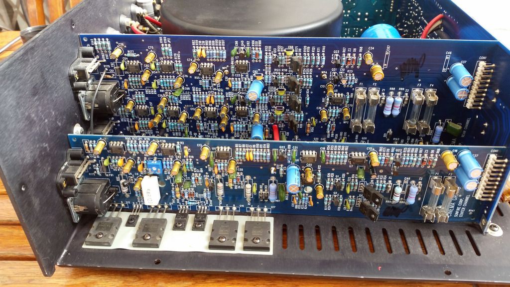
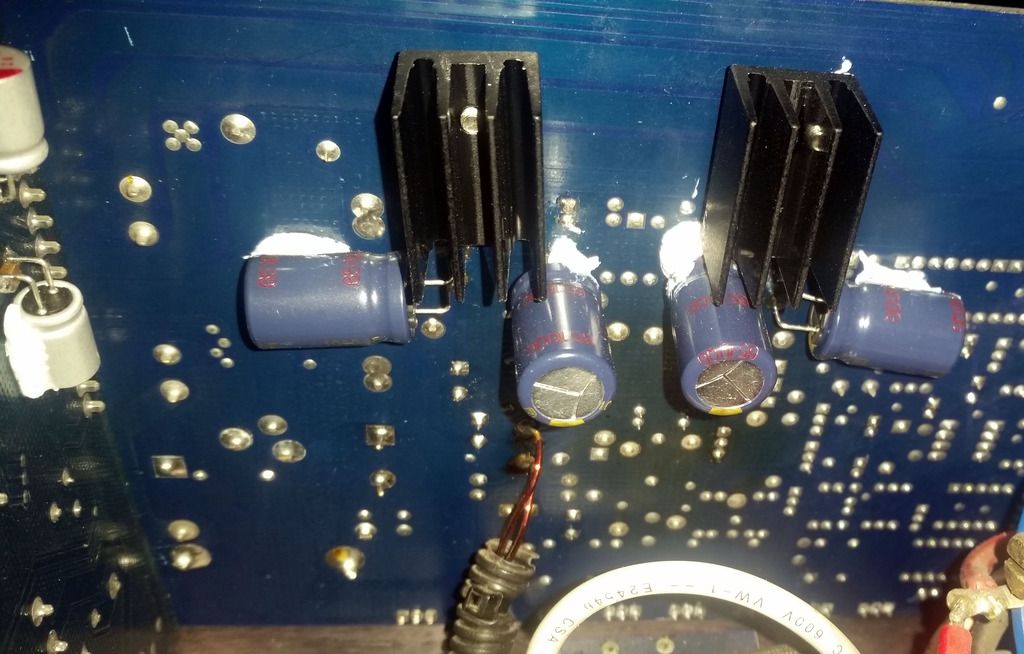
The tracking power supply board after recap.
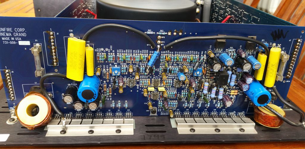
Two channels after recapping & opamp replacement
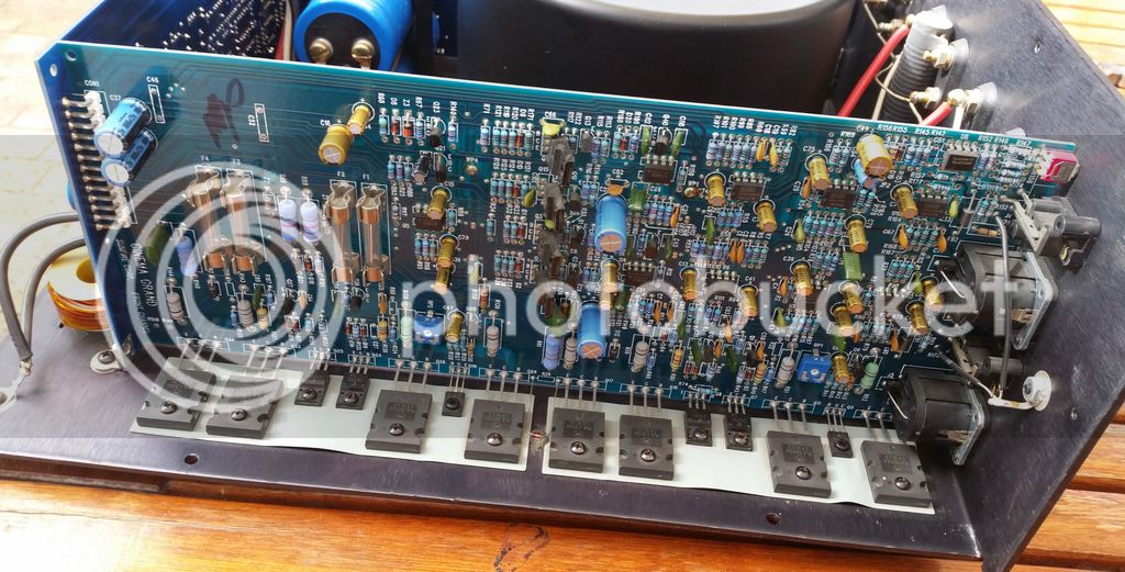
Three more channels afterwards
Since I didn't test throughout it was a relief when everything still worked after I was done.
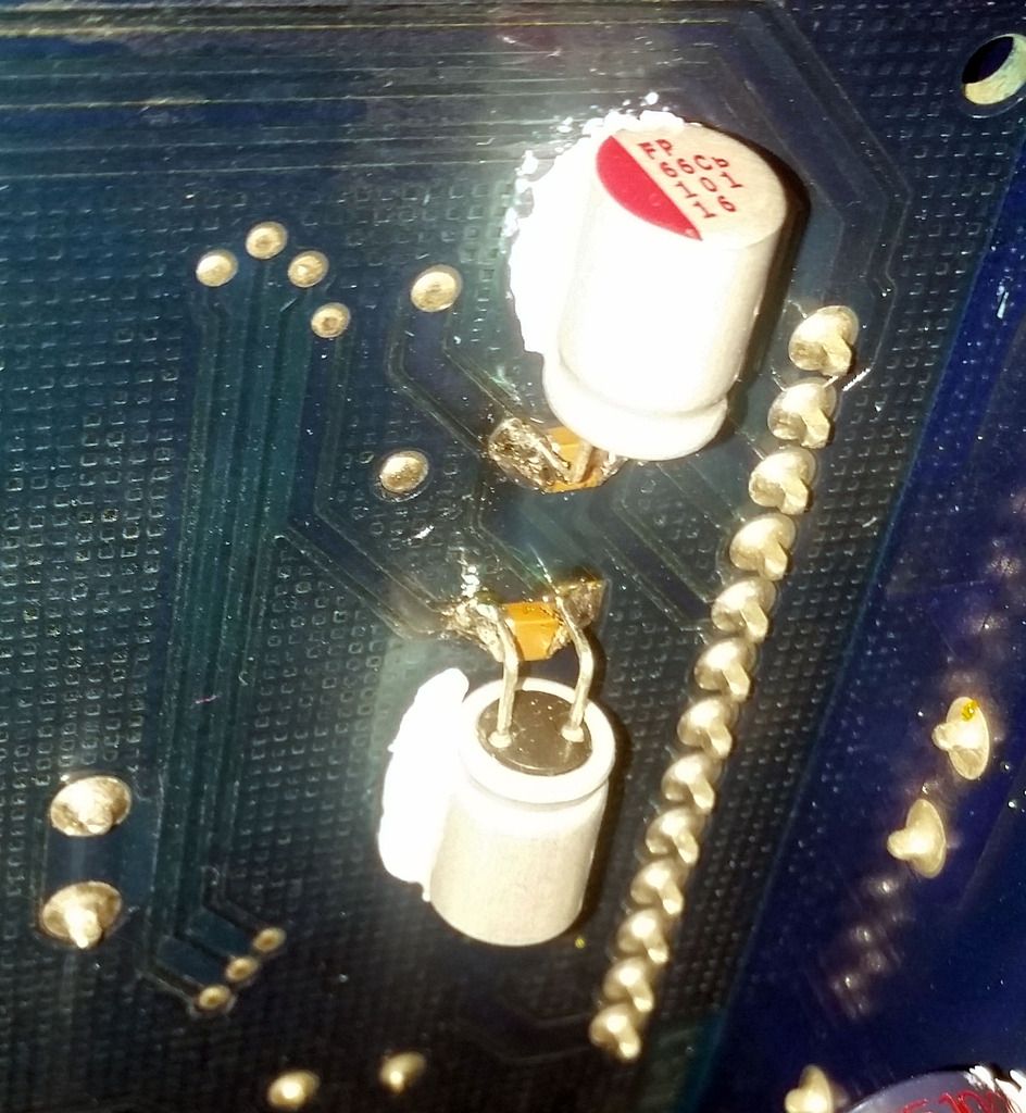
Next up were measurements, and I noticed some spikes from the power supply switching frequency present on the low-level audio signals on the input stages. Not really good. The opamp power is sub-regulated from the main bus power with an emitter-follower regulator on the PSU board and then split to the various amp channel boards. On that board there is just a 1000uF cap per rail and then a 4.7uF electrolytic per rail at each opamp. They are mostly useless for the switching spikes. So, I tack-soldered at the back of the 1000uF caps on each amp board a combination of 100uF polymer electrolytic with very low ESR (much lower than the 1000uF one @ only 7mohm), in parallel with high quality 10uF low-ESR surface mount ceramics. The cans are held in place with RTV silicone - expensive but worth it and much better than regular silicone. Afterwards the spikes were all but gone. I considered adding ceramics at the opamps too but it really wasn't necessary anymore. The local 4.7uF caps are anyway good enough and much better than in many other products.
Opamp power cleanup of one amp board
By now I should have just closed the box but I was not really happy with how hot some of the caps were getting. Despite the amp still having sounded OK with the original junk and the new ones being much higher rated, I still didn't like it. The heat mainly came from the TO220 BJT's used for dropping the opamp power from 84V to 12V (can be seen in the top right corner of the PSU board picture). These BJT's have no heatsinking and just heat up the PCB and the components near them. In addition, these poor TO220's got very hot themselves that also isn't good for their own lifespan.
So, a triple solution was found:
1) Add an extra set of capacitors in parallel at the rear of the PCB that will not get as hot since they are isolated with a blob of RTV.
2) Move the transistors to the back of the board instead of the front to have them further away from all the caps at the front that they heat up
3) Bolt heatsinks to the transistors and keep them in place with RTV to make them run cooler and also radiate more heat into the air instead of the PCB
The end result: both the caps and the regulators now run much cooler. There also is even less ripple on the power rails because of the additional capacitance.
Finally all good and ready for many more years of faithful service") It was not a cheap exercise; the parts alone were almost R2k and the total time spent on replacing, testing and figuring out the circuits were over a hundred hours in total too that puts it purely in the hobby domain. So while it was fun and I haven't done a recap in many years, I won't do it again any time soon..
It was not a cheap exercise; the parts alone were almost R2k and the total time spent on replacing, testing and figuring out the circuits were over a hundred hours in total too that puts it purely in the hobby domain. So while it was fun and I haven't done a recap in many years, I won't do it again any time soon..
The amp was kindly donated by Spurge after it went down in flames when a loose bolt inside blew up the complex tracking power supply. First step was to fix that, which involved replacing all the MOSFET's and a few small-signal transistors. That's not the focus of the thread though.
Despite the amp working fine after, I noticed some electrolytic caps on the PSU being completely discoloured from heat from nearby regulating transistors. Googling revealed this to be a common problem so I thought I would recap, and replace the whole lot while at it. The only ones I retained were the main bus caps since they did not get hot at all, finding suitable replacements that would fit in the brackets was not possible, and the regulated supply meant that the reliance on the caps were much less than with a conventional amplifier linear supply.
[the irony of this amp is that because it has a tracking PSU the amp output stage runs extremely cool. It's just some of the other electronics that run hot]
Did not realize how much work it would turn out to be: there are easily over a 100 caps and just finding suitable substitutes of correct capacitance, voltage and diameter took a lot of time. While I was at it I also replaced all the critical TL072 dual opamps with Burr-Brown OPA2134, which at 3 per channel meant a further 15 in total.
The amp PCB's are all soldered together and removing is a huge task, so all the work was done with the boards in place. That meant some really creative angling with the soldering iron and solder pump.
The stock caps were regular Chinese 85degree junk; the replacements were all chosen as 105degree types, and the ones located in hot zones are 125degree types with extended lifespan (10,000hours at 125degrees) to make sure that they will hardly ever deteriorate in the future. All caps were Panasonic, Nichicon and Vishay.
The tracking power supply board after recap.
Two channels after recapping & opamp replacement
Three more channels afterwards
Since I didn't test throughout it was a relief when everything still worked after I was done.
Next up were measurements, and I noticed some spikes from the power supply switching frequency present on the low-level audio signals on the input stages. Not really good. The opamp power is sub-regulated from the main bus power with an emitter-follower regulator on the PSU board and then split to the various amp channel boards. On that board there is just a 1000uF cap per rail and then a 4.7uF electrolytic per rail at each opamp. They are mostly useless for the switching spikes. So, I tack-soldered at the back of the 1000uF caps on each amp board a combination of 100uF polymer electrolytic with very low ESR (much lower than the 1000uF one @ only 7mohm), in parallel with high quality 10uF low-ESR surface mount ceramics. The cans are held in place with RTV silicone - expensive but worth it and much better than regular silicone. Afterwards the spikes were all but gone. I considered adding ceramics at the opamps too but it really wasn't necessary anymore. The local 4.7uF caps are anyway good enough and much better than in many other products.
Opamp power cleanup of one amp board
By now I should have just closed the box but I was not really happy with how hot some of the caps were getting. Despite the amp still having sounded OK with the original junk and the new ones being much higher rated, I still didn't like it. The heat mainly came from the TO220 BJT's used for dropping the opamp power from 84V to 12V (can be seen in the top right corner of the PSU board picture). These BJT's have no heatsinking and just heat up the PCB and the components near them. In addition, these poor TO220's got very hot themselves that also isn't good for their own lifespan.
So, a triple solution was found:
1) Add an extra set of capacitors in parallel at the rear of the PCB that will not get as hot since they are isolated with a blob of RTV.
2) Move the transistors to the back of the board instead of the front to have them further away from all the caps at the front that they heat up
3) Bolt heatsinks to the transistors and keep them in place with RTV to make them run cooler and also radiate more heat into the air instead of the PCB
The end result: both the caps and the regulators now run much cooler. There also is even less ripple on the power rails because of the additional capacitance.
Finally all good and ready for many more years of faithful service
It was not a cheap exercise; the parts alone were almost R2k and the total time spent on replacing, testing and figuring out the circuits were over a hundred hours in total too that puts it purely in the hobby domain. So while it was fun and I haven't done a recap in many years, I won't do it again any time soon..