Another lockdown completion: this is a DIY amplifier build that spanned 13 years. It started in 2007 when I told my father he can get a better DIY integrated amplifier than his Arcam Alpha 10/10P biamp combo for a reasonable material cost.
I had a lot of ideas but only limited practical experience back then, so the amp got developed to a 95% completion level but never fully complete and with some bugs.
So, after my father's passing it stood for long in a cupboard until I decided to finish it plus address a few issues. It was tempting to redo everything, so it took some self-control to limit what is thrown out to a minimum. In the end I re-did the main preamp PCB, soft-start PCB, and control module PCB.
The original idea was for a separate pre and power amp. That got dropped due to cost and mechanical reasons. The intention though was for the amp to be in a closed cupboard out of sight, but still visible indication of volume. So I built it as an integrated amp, but with the external part being only the volume control circuit, outside of the audio signal path.
Specifications were not too shabby:
- Fully dual mono construction. Nothing is shared except the AC power input, MCU and chassis. Even the control circuits from the MCU are isolated. It was at a time when I was chasing windmills of not sharing any power supplies or grounds before realizing the money and effort are better spent elsewhere.
- Hypex UcD400 amplifier modules, upgraded to hell & gone. Opamps were replaced with AD8066, caps were replaced with Panasonic FC's and bypassed with Vishay MKP1837 and the circuit hacked to have the opamp power supplied by an external dedicated power supply instead of derived from the amplifier rails.
- Twin 800VA toroidals, mounted on Deflex absorber sheets.
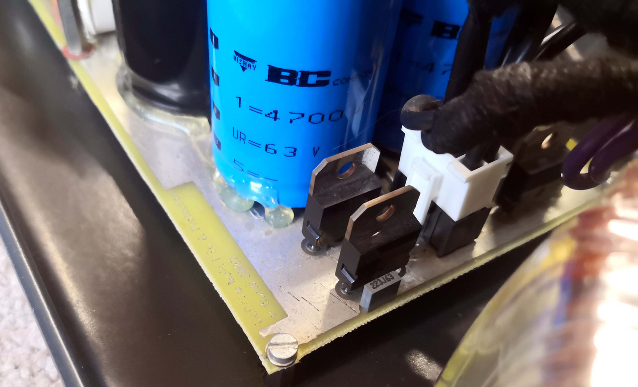
- Power supply built with BHC Aerovox and Philips electrolytics, bypassed with Mundorf M-Caps. Power supply also includes a super fast-acting DC offset protection circuit. Rectifiers are some special soft-recovery high current types.
- Twin 50VA toroidals each with three secondaries going to a small PSU & regulator board each: 5V digital for the control preamplifier, +-15V analog for the preamplifier & output buffer, and +-15V analog for the Hypex amplifier input buffer. All have their own rectifiers, CRC filters and LM317/337 regulators.
- Preamplifier board consisting of a central microcontroller, powered by the soft-start power supply. The MCU then controls via SPI the two preamp chips (PGA2320). The SPI is isolated with iCouplers, hence the dual digital power rails.
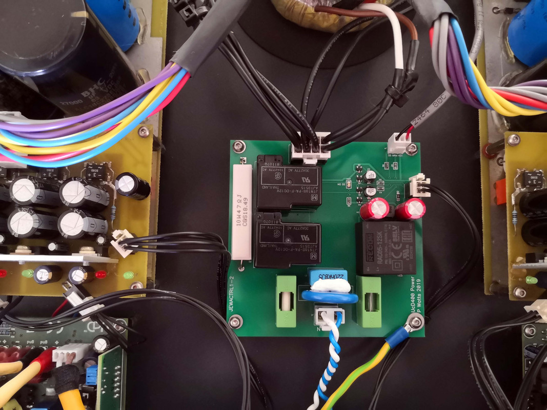
- Soft-start PCB with a very high efficiency AC-DC power supply, two oversized industrial relays (one to cut out the mains power and one to bypass a power resistor), fuses, a basic X2 cap and way oversized MOV. I do not use series inductors or common-mode chokes on power amps unless EMI measurements dictates so. The AC-DC PSU has to be high efficiency since it's the standby power for the MCU that is on all the time.
The preamp is fully differential from input to output, including the stereo volume control IC which uses one channel per phase. The PGA2320 output drives the Hypex input directly, everything DC-coupled. Input from the XLR plugs to the PGA2320 is done with a differential OPA1632 opamp.
- Hookup wire from XLR to preamp is silver-coated copper with Teflon insulation. Speaker cable and interconnect wire is VdH. The black power cabling are ready-made cables from Samtec. All critical cabling is hard-wired (which proved a real pain, never again).
- AC distribution module incorporating relay control and soft-start, controlled from the MCU on the preamp board.
- Solid 3mm steel chassis, powder-coated.
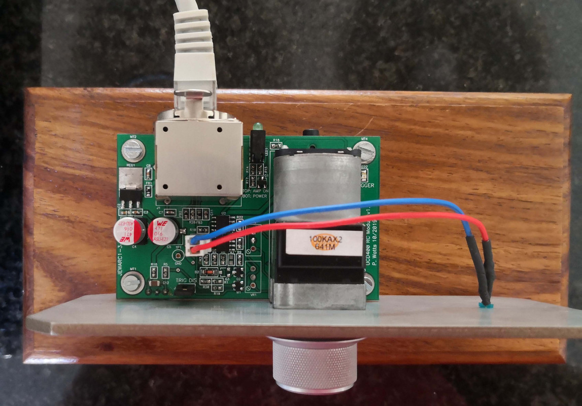
The preamp concept I thought was quite novel at the time: in the external module is a motorized pot, small MCU and IR receiver. This module connects to the amp with a CAT5 cable (cable only, Ethernet is not used). The cable sources power to the module, and the pot on the module scales a 5V reference voltage between 0V and 5V. This analog scaled voltage is then sent back to the amp through the cable which then digitizes it with an ADC to an 8bit value that sets the preamp gain. Since it's a motorized pot, the volume is set either manually or with IR. The amp can also be powered off/on with either IR or a 12V trigger input. All sorts of protection is on the module and the preamp PCB for EMI, ESD, overcurrent, cable plugging/unplugging etc.
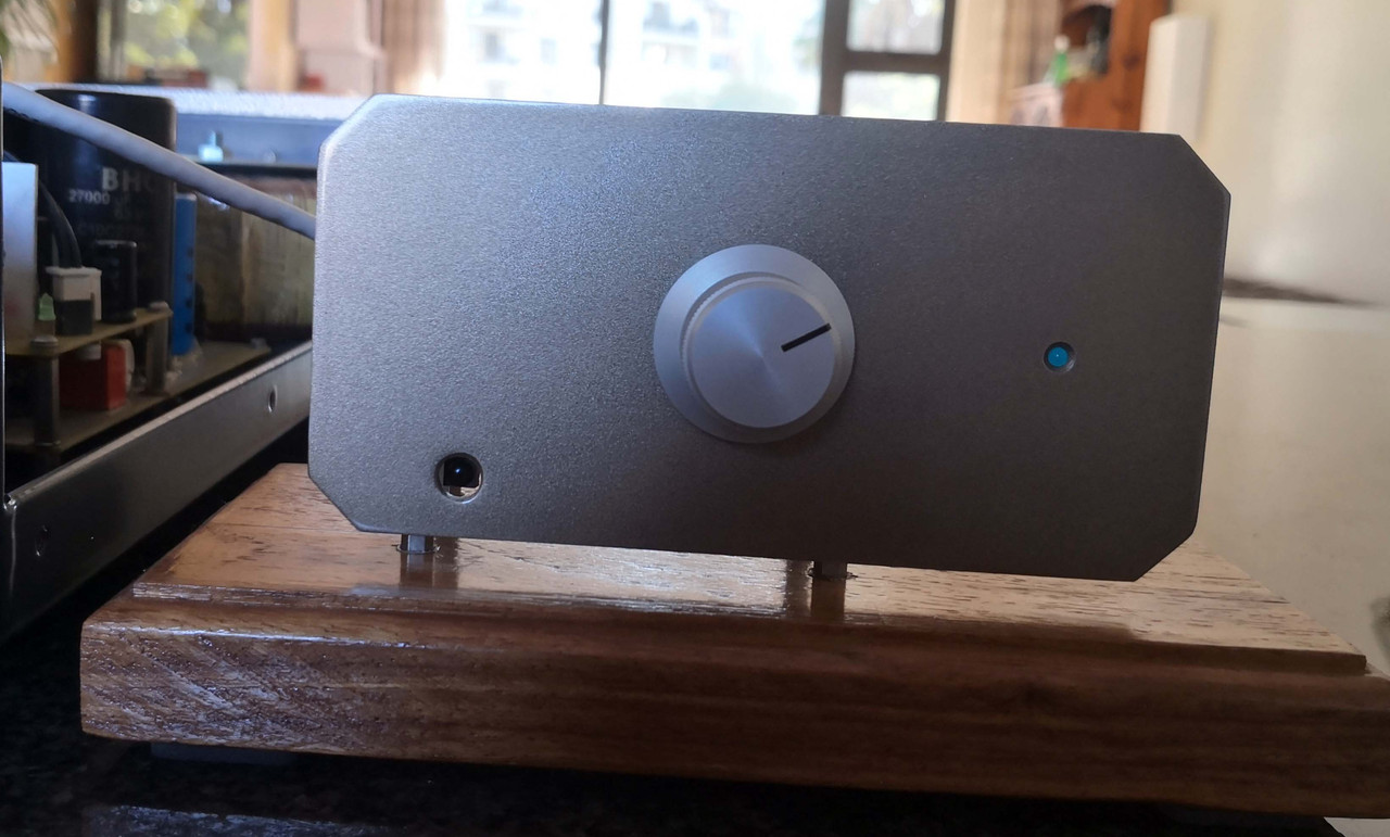
The control module was deliberately made "naked" since my father liked showing it to visitors, so it just got a wooden plinth and metal faceplate with power LED. The main amp also only has a power LED.
Of course, when one fixes some problems you introduce others so unfortunately some PCB mods on the new preamp PCB were needed. Another snag is that the motorized pot has to be linear (since it controls a dB-scaled device), but the Alps linear pots are not linear at all: the resistance remains the same for much of the travel, so the gain adjustment is not as gradual as I'd have liked. In hindsight I should have rather used a shaft encoder.
Otherwise, everything works perfectly now even in extreme cases of plugging and unplugging the CAT5 cable in the middle of operation or very long cables etc. Sound quality is also excellent - I didn't do a before and after test but it already performed well before and after the revamp (which made changes like switching from AC to DC coupling and better signal routing and component quality etc.) the quality should be even better.
Pics & descriptions below:
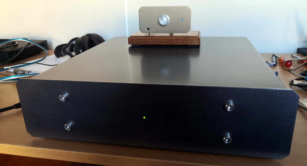
Final amp, closed
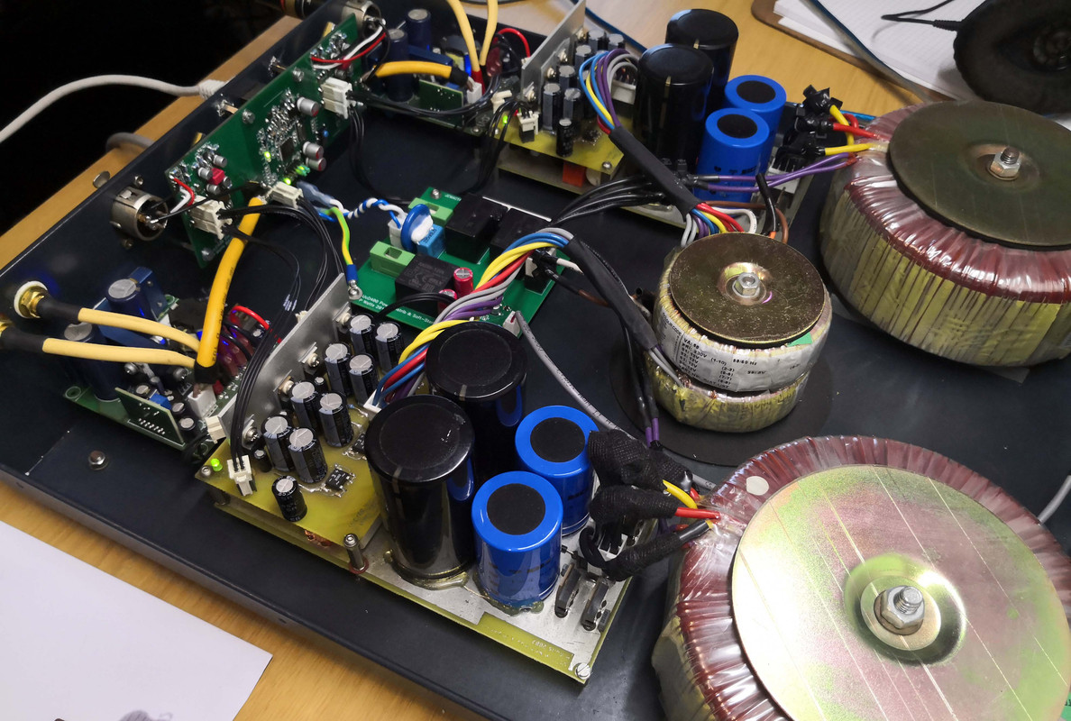
Interior
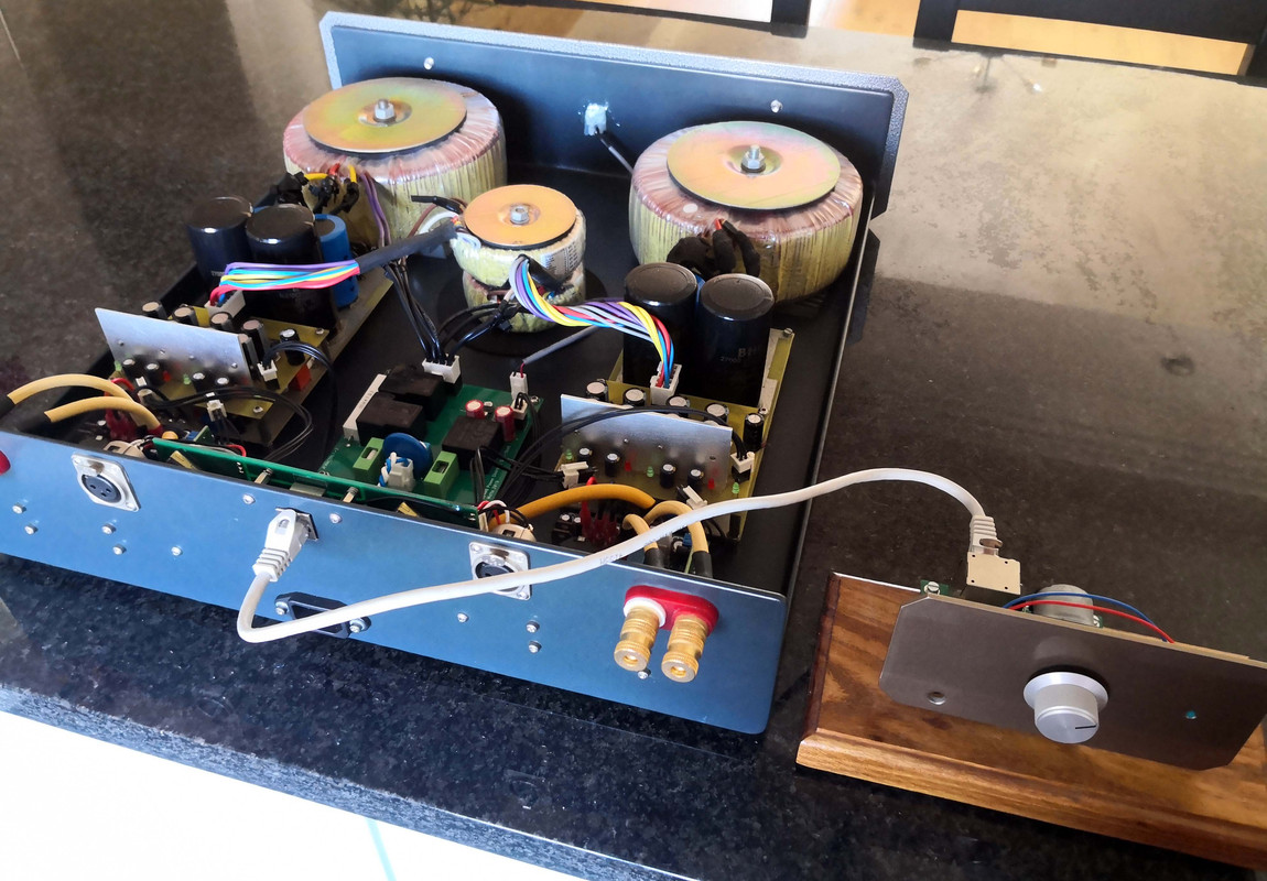
Interior & control module. For the intended use the CAT5 cable would be 2m or so, not this short.
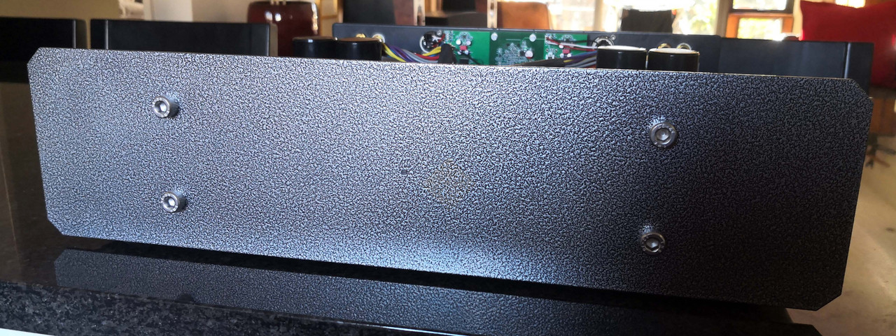
Amp front
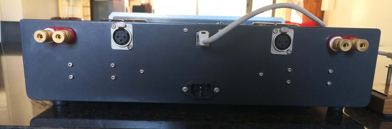
Amp rear
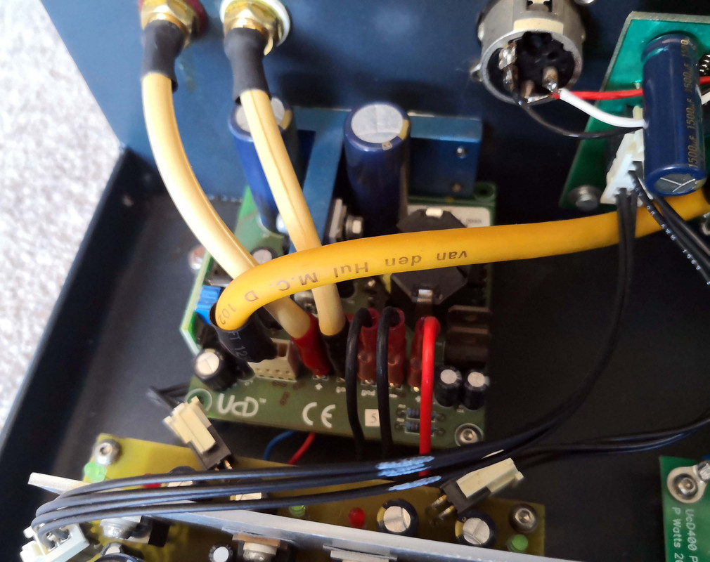
Amplifiers. Power cables coming in at the right; note the extra cable at the left for the dedicated amplifier input stage power
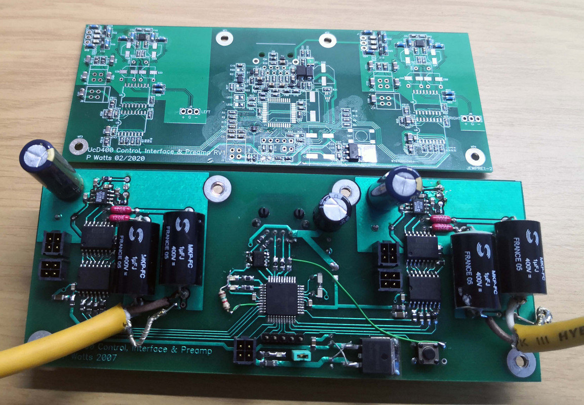
Old preamp PCB (bottom) vs. new PCB in progress (top)
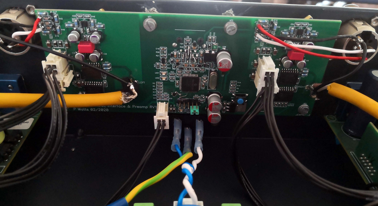
New preamp PCB, installed
Soft-start PCB
Amp rectifiers & caps
Control module front
Control module top
I had a lot of ideas but only limited practical experience back then, so the amp got developed to a 95% completion level but never fully complete and with some bugs.
So, after my father's passing it stood for long in a cupboard until I decided to finish it plus address a few issues. It was tempting to redo everything, so it took some self-control to limit what is thrown out to a minimum. In the end I re-did the main preamp PCB, soft-start PCB, and control module PCB.
The original idea was for a separate pre and power amp. That got dropped due to cost and mechanical reasons. The intention though was for the amp to be in a closed cupboard out of sight, but still visible indication of volume. So I built it as an integrated amp, but with the external part being only the volume control circuit, outside of the audio signal path.
Specifications were not too shabby:
- Fully dual mono construction. Nothing is shared except the AC power input, MCU and chassis. Even the control circuits from the MCU are isolated. It was at a time when I was chasing windmills of not sharing any power supplies or grounds before realizing the money and effort are better spent elsewhere.
- Hypex UcD400 amplifier modules, upgraded to hell & gone. Opamps were replaced with AD8066, caps were replaced with Panasonic FC's and bypassed with Vishay MKP1837 and the circuit hacked to have the opamp power supplied by an external dedicated power supply instead of derived from the amplifier rails.
- Twin 800VA toroidals, mounted on Deflex absorber sheets.
- Power supply built with BHC Aerovox and Philips electrolytics, bypassed with Mundorf M-Caps. Power supply also includes a super fast-acting DC offset protection circuit. Rectifiers are some special soft-recovery high current types.
- Twin 50VA toroidals each with three secondaries going to a small PSU & regulator board each: 5V digital for the control preamplifier, +-15V analog for the preamplifier & output buffer, and +-15V analog for the Hypex amplifier input buffer. All have their own rectifiers, CRC filters and LM317/337 regulators.
- Preamplifier board consisting of a central microcontroller, powered by the soft-start power supply. The MCU then controls via SPI the two preamp chips (PGA2320). The SPI is isolated with iCouplers, hence the dual digital power rails.
- Soft-start PCB with a very high efficiency AC-DC power supply, two oversized industrial relays (one to cut out the mains power and one to bypass a power resistor), fuses, a basic X2 cap and way oversized MOV. I do not use series inductors or common-mode chokes on power amps unless EMI measurements dictates so. The AC-DC PSU has to be high efficiency since it's the standby power for the MCU that is on all the time.
The preamp is fully differential from input to output, including the stereo volume control IC which uses one channel per phase. The PGA2320 output drives the Hypex input directly, everything DC-coupled. Input from the XLR plugs to the PGA2320 is done with a differential OPA1632 opamp.
- Hookup wire from XLR to preamp is silver-coated copper with Teflon insulation. Speaker cable and interconnect wire is VdH. The black power cabling are ready-made cables from Samtec. All critical cabling is hard-wired (which proved a real pain, never again).
- AC distribution module incorporating relay control and soft-start, controlled from the MCU on the preamp board.
- Solid 3mm steel chassis, powder-coated.
The preamp concept I thought was quite novel at the time: in the external module is a motorized pot, small MCU and IR receiver. This module connects to the amp with a CAT5 cable (cable only, Ethernet is not used). The cable sources power to the module, and the pot on the module scales a 5V reference voltage between 0V and 5V. This analog scaled voltage is then sent back to the amp through the cable which then digitizes it with an ADC to an 8bit value that sets the preamp gain. Since it's a motorized pot, the volume is set either manually or with IR. The amp can also be powered off/on with either IR or a 12V trigger input. All sorts of protection is on the module and the preamp PCB for EMI, ESD, overcurrent, cable plugging/unplugging etc.
The control module was deliberately made "naked" since my father liked showing it to visitors, so it just got a wooden plinth and metal faceplate with power LED. The main amp also only has a power LED.
Of course, when one fixes some problems you introduce others so unfortunately some PCB mods on the new preamp PCB were needed. Another snag is that the motorized pot has to be linear (since it controls a dB-scaled device), but the Alps linear pots are not linear at all: the resistance remains the same for much of the travel, so the gain adjustment is not as gradual as I'd have liked. In hindsight I should have rather used a shaft encoder.
Otherwise, everything works perfectly now even in extreme cases of plugging and unplugging the CAT5 cable in the middle of operation or very long cables etc. Sound quality is also excellent - I didn't do a before and after test but it already performed well before and after the revamp (which made changes like switching from AC to DC coupling and better signal routing and component quality etc.) the quality should be even better.
Pics & descriptions below:
Final amp, closed
Interior
Interior & control module. For the intended use the CAT5 cable would be 2m or so, not this short.
Amp front
Amp rear
Amplifiers. Power cables coming in at the right; note the extra cable at the left for the dedicated amplifier input stage power
Old preamp PCB (bottom) vs. new PCB in progress (top)
New preamp PCB, installed
Soft-start PCB
Amp rectifiers & caps
Control module front
Control module top