Following the success of my 6ch amp (link below) and having some parts left, I thought I'd do a little (well 500W/ch) stereo desktop power amp with little effort and cost. Inputs are still XLR only. Won't go into too much detail as there is so much shared with the 6ch version.
https://www.avforums.co.za/index.php/topic,85141.msg973816.html#msg973816
Breakdown of parts below:
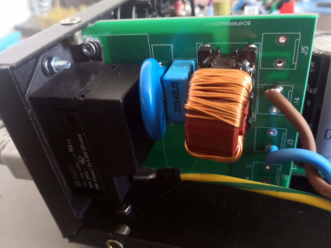
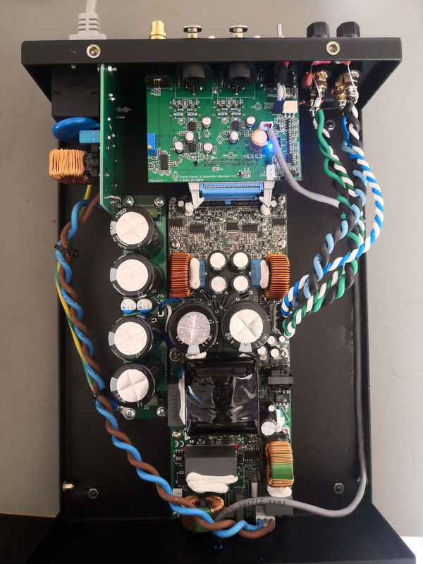
AC input module is unchanged with fused & switched inlet, MOV, X-capacitor, common-mode choke & bleed resistor. The output wiring just got hard-soldered since the application is simple enough not to justify another connector.
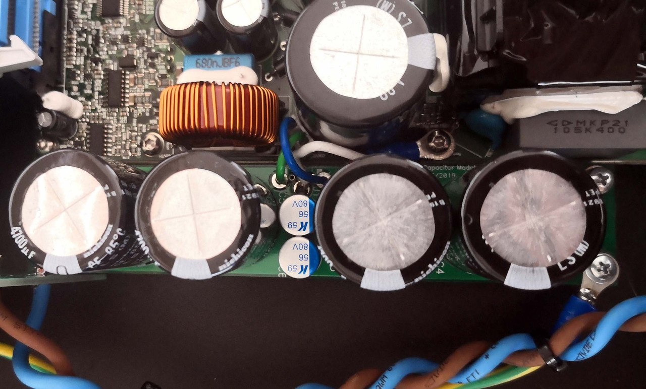
DC stiffening capacitor bank also unchanged with 4x 4700uF low-ESR caps in parallel with 56uF polymer electrolytics.
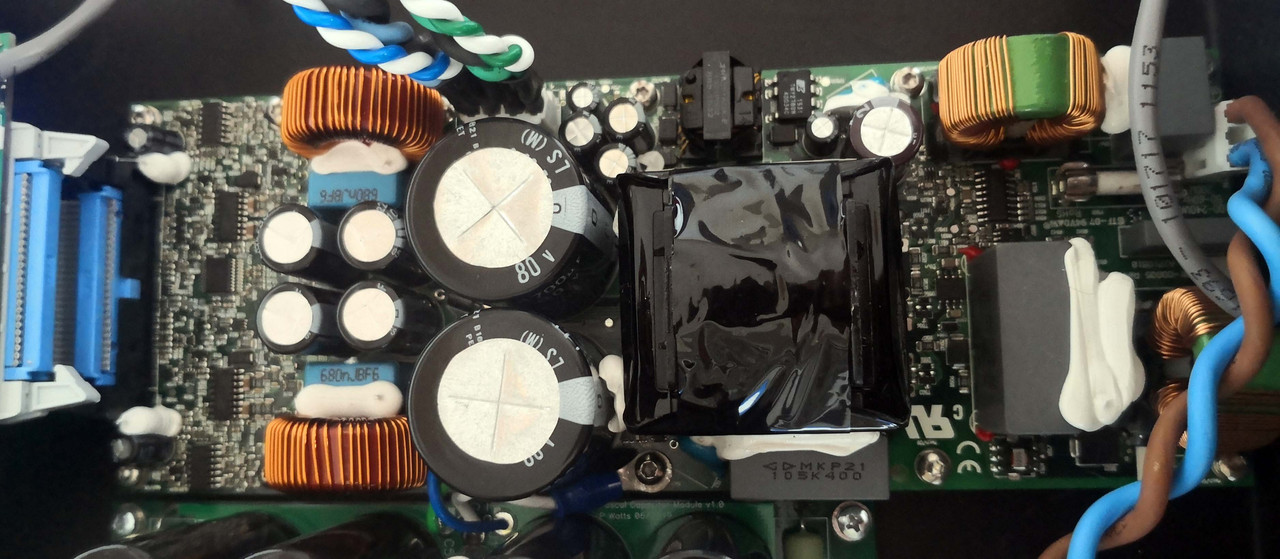
- The Pascal amplifier module is a resurrected one that has had a few thousand hours on the clock. I did the same modifications as on the 6ch amp, but on this one I also replaced ALL the electrolytics with not just the lowest ESR available but also the longest rated lifespan. Unlike non-switching amps, capacitors in swithing applications live a very hard life and there is merit in recapping when there is no failure. This amp will comfortably play all day, every day, for decades.
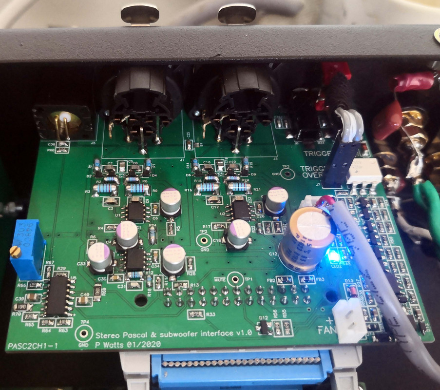
- Input module is 90% identical to the previous model, but I made a small addition of a trigger output (directly connected to the input to avoid splitting a source trigger cable from turning on the amp and a sub) as well as a summing circuit with variable gain. This is to be used for a subwoofer output channel for the following reasons:
1) No additional preamp loading to the sub
2) No expensive and bulky XLR cable splitters needed
3) No ground loop issues of having RCA's on the splitters since few small subs have XLR inputs
4) Summing at the amp means only a single cable to the sub instead of two
5) Variable gain on the circuit to optimize the gain range of the sub
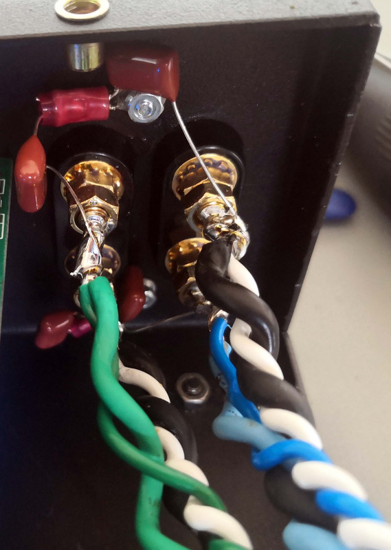
- Output terminals are bog-standard binding posts, but with a common-mode filter to chassis added. This is to reduce EMI, which is important for me since the amp will be used in my deskop environment where I don't want switching residuals broadcast on the cable to affect my testing gear.
Cabling is the same as before, high-quality ribbon plugs with silver-coated ribbon cable, thick Teflon-insulated silver-coated copper speaker cable and very thick AC cable.
Here's a total view of the inside:
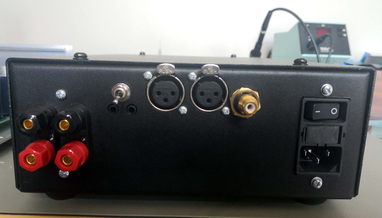
At the rear is just the basics: two trigger terminals, trigger override switch, XLR inputs, speaker outputs, sub output and AC input.
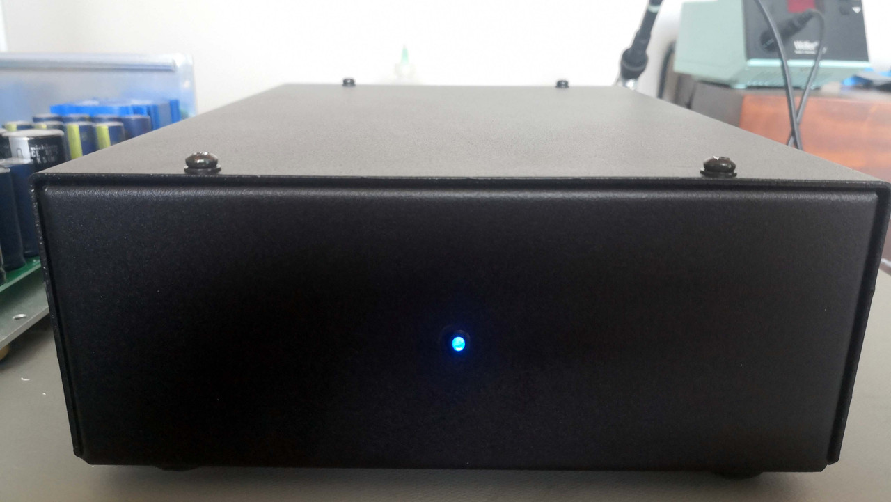
Front is even more minimalist: just a single blue LED. Blue purely because I had one in my junkbox.
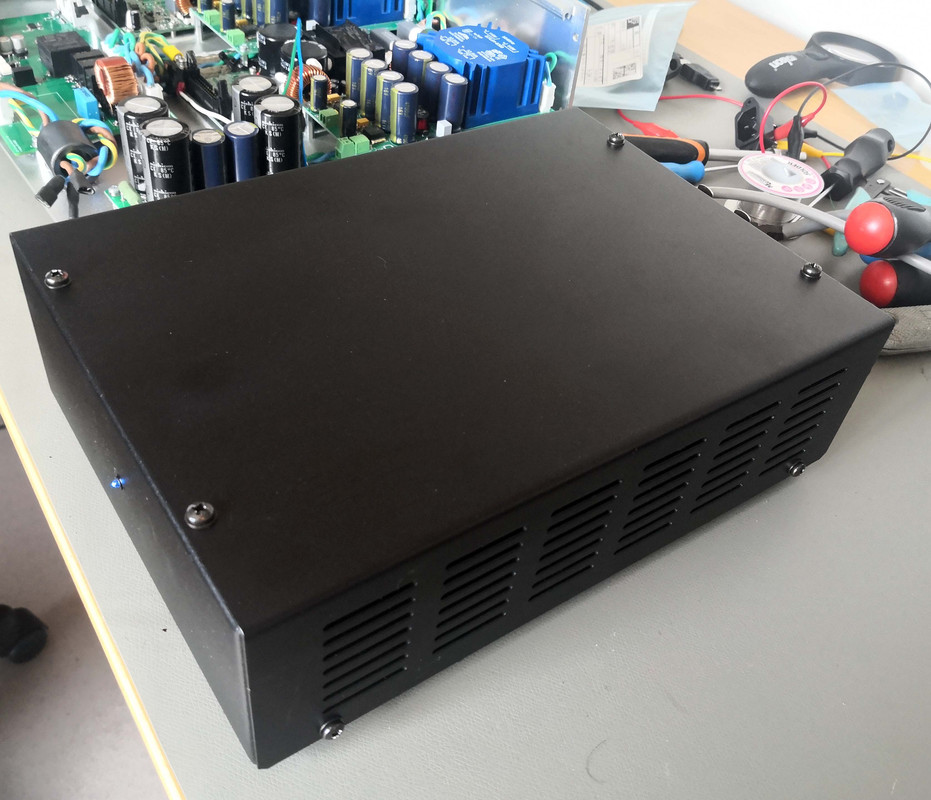
Chassis is spartan to say the least, this is because it was done at minimal cost. Bent & punched 1.6mm sheet steel; powdercoated. No luxuries like silkscreening or recessed screws and that's just fine for the application.
Quality? Haven't listened yet, but I expect it to be every bit as good as the 6ch version or perhaps slightly better given that there's only one amp and better overall layout plus the improved amplifier caps.
https://www.avforums.co.za/index.php/topic,85141.msg973816.html#msg973816
Breakdown of parts below:
AC input module is unchanged with fused & switched inlet, MOV, X-capacitor, common-mode choke & bleed resistor. The output wiring just got hard-soldered since the application is simple enough not to justify another connector.
DC stiffening capacitor bank also unchanged with 4x 4700uF low-ESR caps in parallel with 56uF polymer electrolytics.
- The Pascal amplifier module is a resurrected one that has had a few thousand hours on the clock. I did the same modifications as on the 6ch amp, but on this one I also replaced ALL the electrolytics with not just the lowest ESR available but also the longest rated lifespan. Unlike non-switching amps, capacitors in swithing applications live a very hard life and there is merit in recapping when there is no failure. This amp will comfortably play all day, every day, for decades.
- Input module is 90% identical to the previous model, but I made a small addition of a trigger output (directly connected to the input to avoid splitting a source trigger cable from turning on the amp and a sub) as well as a summing circuit with variable gain. This is to be used for a subwoofer output channel for the following reasons:
1) No additional preamp loading to the sub
2) No expensive and bulky XLR cable splitters needed
3) No ground loop issues of having RCA's on the splitters since few small subs have XLR inputs
4) Summing at the amp means only a single cable to the sub instead of two
5) Variable gain on the circuit to optimize the gain range of the sub
- Output terminals are bog-standard binding posts, but with a common-mode filter to chassis added. This is to reduce EMI, which is important for me since the amp will be used in my deskop environment where I don't want switching residuals broadcast on the cable to affect my testing gear.
Cabling is the same as before, high-quality ribbon plugs with silver-coated ribbon cable, thick Teflon-insulated silver-coated copper speaker cable and very thick AC cable.
Here's a total view of the inside:
At the rear is just the basics: two trigger terminals, trigger override switch, XLR inputs, speaker outputs, sub output and AC input.
Front is even more minimalist: just a single blue LED. Blue purely because I had one in my junkbox.
Chassis is spartan to say the least, this is because it was done at minimal cost. Bent & punched 1.6mm sheet steel; powdercoated. No luxuries like silkscreening or recessed screws and that's just fine for the application.
Quality? Haven't listened yet, but I expect it to be every bit as good as the 6ch version or perhaps slightly better given that there's only one amp and better overall layout plus the improved amplifier caps.