So, something new during lockdown evenings. Design started in December but assembly only begun during lockdown and, not begin able to go out, everything had to be done with what I had at hand in my flat. Since I never would have found the time otherwise, I decided to just do it.
It started with having received a Nuprime DAC-9 that was uneconomical to repair following an 'Eskom incident'. The input MOV turned into a hand grenade and blew to smithereens, AC wiring melted, the transformer completely melted its insulation, the rectifiers, regulators and quite a few other parts were shot. A replacement transformer from Nuprime was ridiculously priced, and any alternatives would have (together with the extensive rework) reduced the unit value too much. So, I decided to have some fun with it by doing a modified repair and reducing the risk of further similar damage, and then use it as a desktop DAC/preamp at my PC.
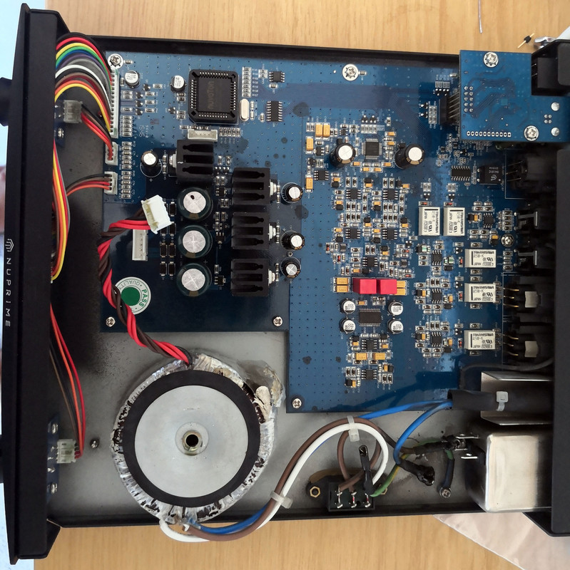
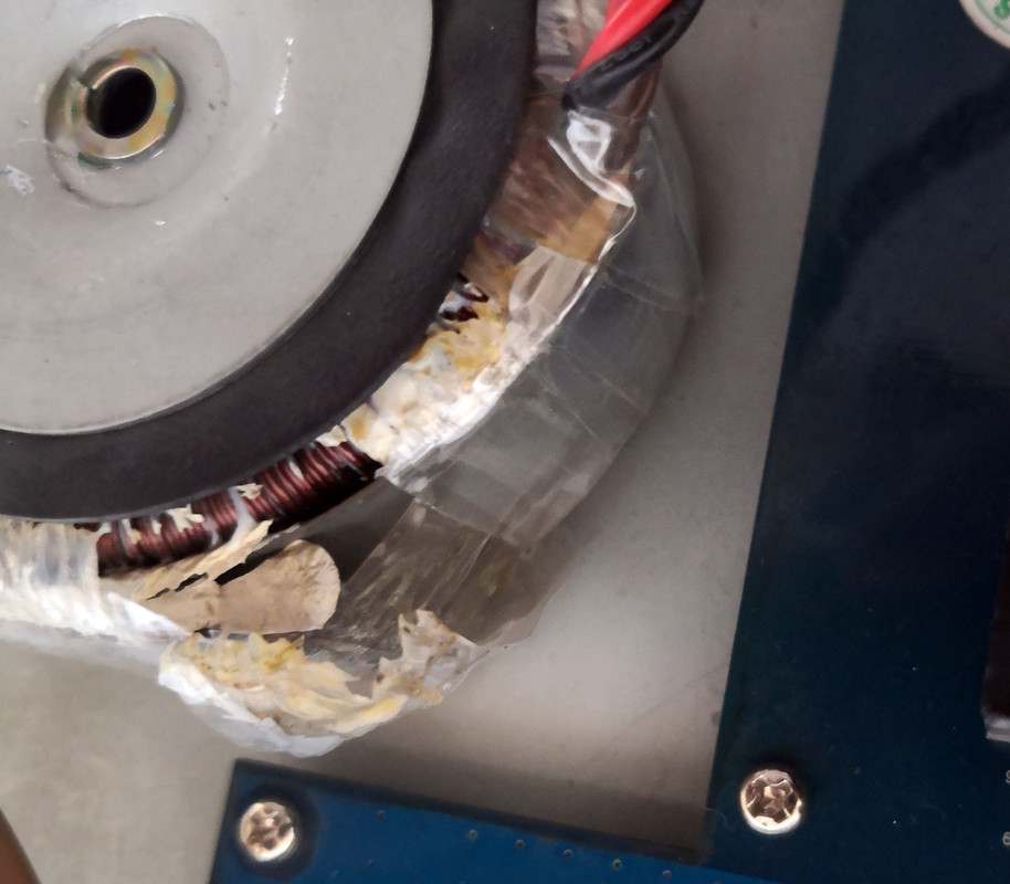
The two pictures below show the original state, after cleaning up all the mess and scorch marks. Bottom right one can still see the remnants of the exploded MOV on the chassis bottom and the melted plugs. Next pic shows the sorry state of the transformer.
First step was replacing the broken rectifiers, regulators and all other parts that popped and powering from a bench. This was a standard repair so nothing exciting.
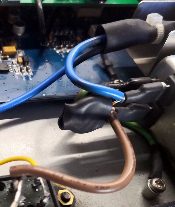
Next was cleaning up the wiring, replacing molten plugs and cables and replacing the MOV. The new one is much higher rated than the puny original and enshrouded in heatshrink to contain the shrapnel should it ever blow again. Replaced wiring is teflon-insulated.
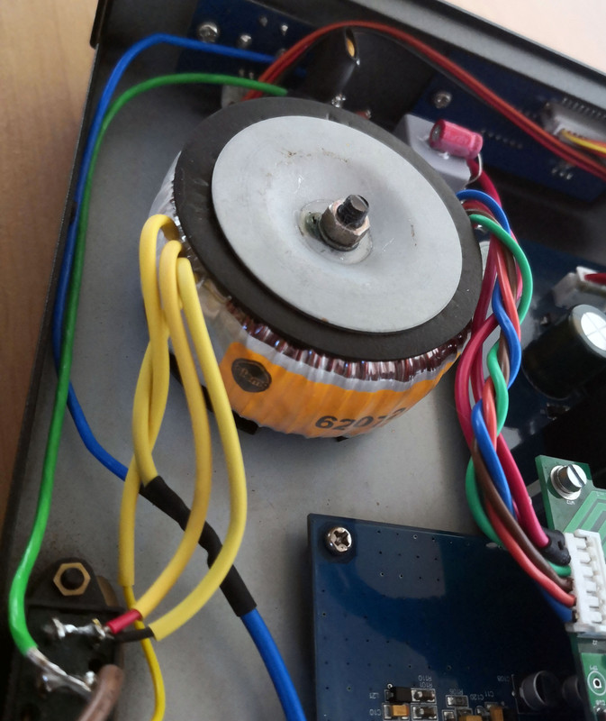
Next was the transformer. The original had triple secondaries and not available off the shelf. One is 7VAC and purely used for control logic and USB. The other is a split-rail and used for the opamps, preamp and DAC. So, I got a new 35VA split-rail transformer from Talema, shown in the picture below. Its windings are quite a bit thicker and overall it looks like a better product than the original. I retained the original cover plate for looks.
For the 7VAC, there was no space for a second separate transformer, so I opted for an encapsulated 10W AC-DC switching module from XP Power. The specific model was chosen based on size, but also because it is rated for Class-B emissions i.e. very little noise that can radiate back to the input mains and into the analog transformer input. I also added a sizeable input filter to improve this even further (MKP cap, inductor & resistor), NTC to reduce inrush and another enshrouded MOV for safety. On the output I added a bulk electrolytic & MKP cap, together with a big TVS diode. The combination of these components should provide decent protection for a variety of mains spikes.
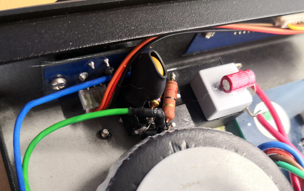
The module is meant for PCB-mount, but I epoxy-glued it onto the chassis bottom and hard-wired the components to the leads. Since it already produces DC, the rectifier diodes on the mainboard were removed to improve efficiency.
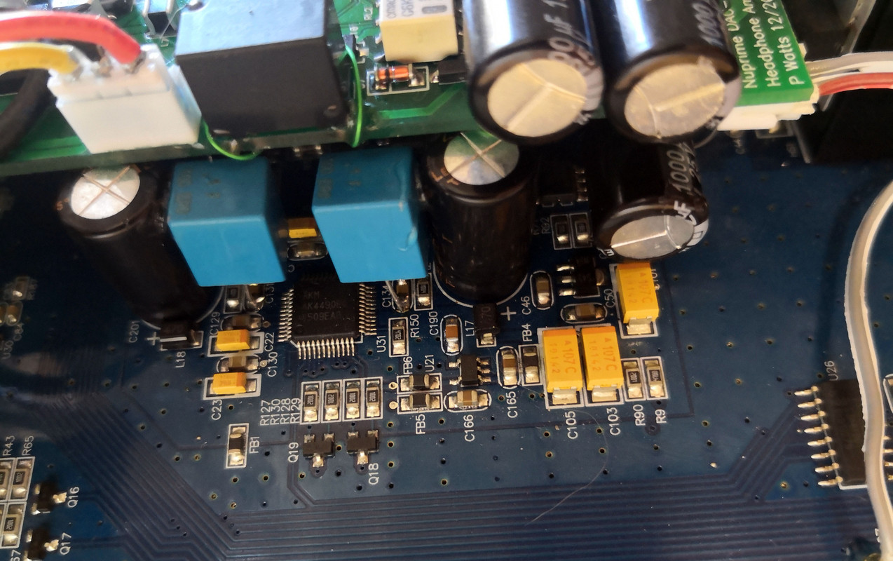
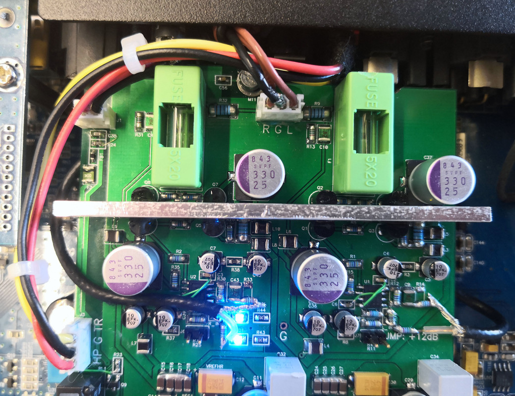
Modding the unit itself was tempting, but the quality of the parts are actually rather good as it is and worthwhile changes would either be too risky or costly to be worthwhile. I did add two Vishay MKP1837 100nF MKP caps to the sensitive DAC Vref rails though, as shown below in blue.
This is where it could have stopped, but I realized I have little use without an output trigger to drive the power amp and subwoofer, and a headphone output.
So, next step: design a PCB that fits in the existing chassis and mounts on top using the existing mounting holes, and drill holes in the back.
Getting the exact dimensions, mounting hole positions and minimum clearance was a bit of a challenge but fortunately the PCB ended up fitting nicely.
Distributing power was a bit of a headache. I eventually decided not to burden the main unit's DC power at all, and have a completely separate and dedicated rectifier, filter caps and regulator stage. The easiest to accomplish this was to route all the power from the transformer and DC brick via the new board and tapping it there. This is shown in the picture below, where the incoming power is at the connector at the bottom, where it is fed to the headphone board, plus routed out to the mainboard at the left.
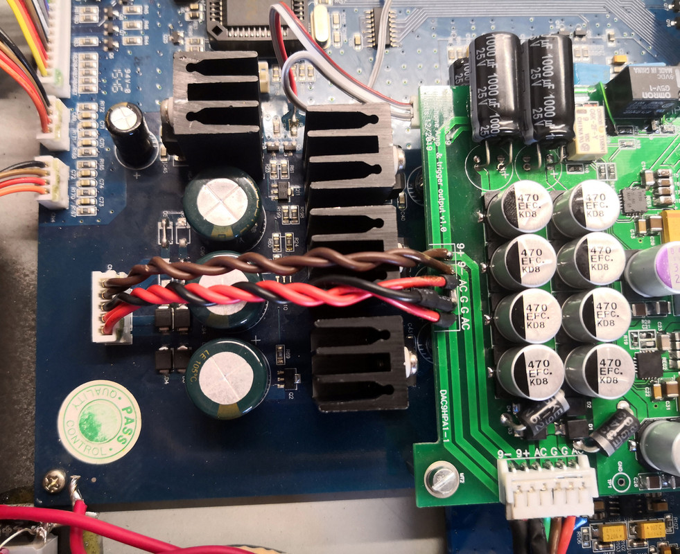
The power for the headphone amp is actually better than what is used in the DAC itself. In total there is 3900uF per rail using a combination of SMT and through-hole caps (two on top and two below), plus two large TVS diodes again for protection. The two QFN surface-mount regulators are among the lowest-noise integrated regulators available; far better than the LM7812 & LM7912 used on the mainboard. Filter caps are a combination of ceramic, tantalum and OS-CON electrolytic where most appropriate. The 2-wire ribbon cable at the bottom and the green mod wires had to be added afterwards to disable the circuit in standby mode to save power.
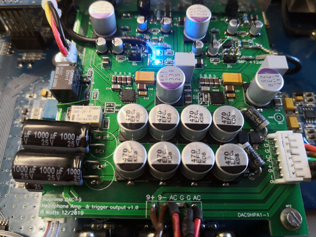
The headphone amp itself uses an opamp input buffer, followed by a gain stage using an opamp with a discrete class-A output stage. The gain stage has an optional +12dB pad for inefficient headphones that can be selected with jumpers. Design is DC-coupled throughout, with fuses on the output for protection. The picture below shows the opamps at the top. Decoupling and filtering is extensive with LCR filters for both the opamps and output stage. Passives used in the signal path are SMT MELF metal film resistors and mica caps.
Bugs of course are always present when designing things in a rush: at the opamps I accidentally swapped the power rails in the design and had to carefully swap them back with short mod wires. The original intention was also for a single-ended input, but ground loops added unacceptable hum so I had to change the input buffers to be driven in differential-mode which fixed it. This did lead to the unsightly coax cables snaking around and hard-wired to the resistors as opposed to coming in from below as intended.
Above the opamps is the output stage. The transistors are epoxied to a 3mm thick aluminium bar for heatsinking as well as thermal tracking. At the top left is the trigger output, this is just a relay driving the 9VCDC through a polyfuse and EMI filter. This does mean that the trigger output is 9V instead of 12V, but this is perfectly fine for all of the input triggers I've seen on gear.
Next picture shows the back. Unfortunately there was no room in the chassis for an uninsulated 3.5mm or 6.3mm jack, which I had to live with. So, the headphone output is now a meaty 6.3mm socket on a little umbilical cord. Not great but also no big deal for a static setup. Wires are silver-coated copper with Teflon insulation.
At the right of the wires is the trigger output connector. Lack of proper tools did mean the nut and chassis got a little damaged.
At the left of the wires is the mode select toggle switch. This is a triple-throw switch:
- middle position disables both the trigger output and cuts the power to headphone amp stage.
- top position enables the trigger output and cuts the headphone power, since one will not need headphones and speakers simultaneously
- conversely, bottom position enables the headphone power and disables the output trigger.
And, below is the full result in its entirety:
Overall, I'm very happy with the result. The unit still has all its original functionality (perhaps even a little better), is much better protected and now has the additional features I wanted. The headphone circuit is dead-quiet and sounds great. Visually the wiring and mechanics could definitely have been better had I had access to my usual tools at work, but overall I'm quite pleased with the result.
It started with having received a Nuprime DAC-9 that was uneconomical to repair following an 'Eskom incident'. The input MOV turned into a hand grenade and blew to smithereens, AC wiring melted, the transformer completely melted its insulation, the rectifiers, regulators and quite a few other parts were shot. A replacement transformer from Nuprime was ridiculously priced, and any alternatives would have (together with the extensive rework) reduced the unit value too much. So, I decided to have some fun with it by doing a modified repair and reducing the risk of further similar damage, and then use it as a desktop DAC/preamp at my PC.
The two pictures below show the original state, after cleaning up all the mess and scorch marks. Bottom right one can still see the remnants of the exploded MOV on the chassis bottom and the melted plugs. Next pic shows the sorry state of the transformer.
First step was replacing the broken rectifiers, regulators and all other parts that popped and powering from a bench. This was a standard repair so nothing exciting.
Next was cleaning up the wiring, replacing molten plugs and cables and replacing the MOV. The new one is much higher rated than the puny original and enshrouded in heatshrink to contain the shrapnel should it ever blow again. Replaced wiring is teflon-insulated.
Next was the transformer. The original had triple secondaries and not available off the shelf. One is 7VAC and purely used for control logic and USB. The other is a split-rail and used for the opamps, preamp and DAC. So, I got a new 35VA split-rail transformer from Talema, shown in the picture below. Its windings are quite a bit thicker and overall it looks like a better product than the original. I retained the original cover plate for looks.
For the 7VAC, there was no space for a second separate transformer, so I opted for an encapsulated 10W AC-DC switching module from XP Power. The specific model was chosen based on size, but also because it is rated for Class-B emissions i.e. very little noise that can radiate back to the input mains and into the analog transformer input. I also added a sizeable input filter to improve this even further (MKP cap, inductor & resistor), NTC to reduce inrush and another enshrouded MOV for safety. On the output I added a bulk electrolytic & MKP cap, together with a big TVS diode. The combination of these components should provide decent protection for a variety of mains spikes.
The module is meant for PCB-mount, but I epoxy-glued it onto the chassis bottom and hard-wired the components to the leads. Since it already produces DC, the rectifier diodes on the mainboard were removed to improve efficiency.
Modding the unit itself was tempting, but the quality of the parts are actually rather good as it is and worthwhile changes would either be too risky or costly to be worthwhile. I did add two Vishay MKP1837 100nF MKP caps to the sensitive DAC Vref rails though, as shown below in blue.
This is where it could have stopped, but I realized I have little use without an output trigger to drive the power amp and subwoofer, and a headphone output.
So, next step: design a PCB that fits in the existing chassis and mounts on top using the existing mounting holes, and drill holes in the back.
Getting the exact dimensions, mounting hole positions and minimum clearance was a bit of a challenge but fortunately the PCB ended up fitting nicely.
Distributing power was a bit of a headache. I eventually decided not to burden the main unit's DC power at all, and have a completely separate and dedicated rectifier, filter caps and regulator stage. The easiest to accomplish this was to route all the power from the transformer and DC brick via the new board and tapping it there. This is shown in the picture below, where the incoming power is at the connector at the bottom, where it is fed to the headphone board, plus routed out to the mainboard at the left.
The power for the headphone amp is actually better than what is used in the DAC itself. In total there is 3900uF per rail using a combination of SMT and through-hole caps (two on top and two below), plus two large TVS diodes again for protection. The two QFN surface-mount regulators are among the lowest-noise integrated regulators available; far better than the LM7812 & LM7912 used on the mainboard. Filter caps are a combination of ceramic, tantalum and OS-CON electrolytic where most appropriate. The 2-wire ribbon cable at the bottom and the green mod wires had to be added afterwards to disable the circuit in standby mode to save power.
The headphone amp itself uses an opamp input buffer, followed by a gain stage using an opamp with a discrete class-A output stage. The gain stage has an optional +12dB pad for inefficient headphones that can be selected with jumpers. Design is DC-coupled throughout, with fuses on the output for protection. The picture below shows the opamps at the top. Decoupling and filtering is extensive with LCR filters for both the opamps and output stage. Passives used in the signal path are SMT MELF metal film resistors and mica caps.
Bugs of course are always present when designing things in a rush: at the opamps I accidentally swapped the power rails in the design and had to carefully swap them back with short mod wires. The original intention was also for a single-ended input, but ground loops added unacceptable hum so I had to change the input buffers to be driven in differential-mode which fixed it. This did lead to the unsightly coax cables snaking around and hard-wired to the resistors as opposed to coming in from below as intended.
Above the opamps is the output stage. The transistors are epoxied to a 3mm thick aluminium bar for heatsinking as well as thermal tracking. At the top left is the trigger output, this is just a relay driving the 9VCDC through a polyfuse and EMI filter. This does mean that the trigger output is 9V instead of 12V, but this is perfectly fine for all of the input triggers I've seen on gear.
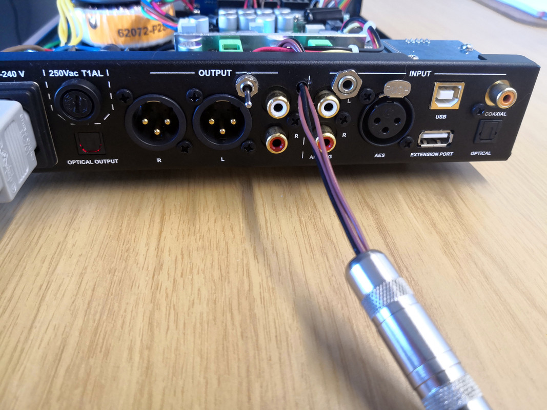
Next picture shows the back. Unfortunately there was no room in the chassis for an uninsulated 3.5mm or 6.3mm jack, which I had to live with. So, the headphone output is now a meaty 6.3mm socket on a little umbilical cord. Not great but also no big deal for a static setup. Wires are silver-coated copper with Teflon insulation.
At the right of the wires is the trigger output connector. Lack of proper tools did mean the nut and chassis got a little damaged.
At the left of the wires is the mode select toggle switch. This is a triple-throw switch:
- middle position disables both the trigger output and cuts the power to headphone amp stage.
- top position enables the trigger output and cuts the headphone power, since one will not need headphones and speakers simultaneously
- conversely, bottom position enables the headphone power and disables the output trigger.
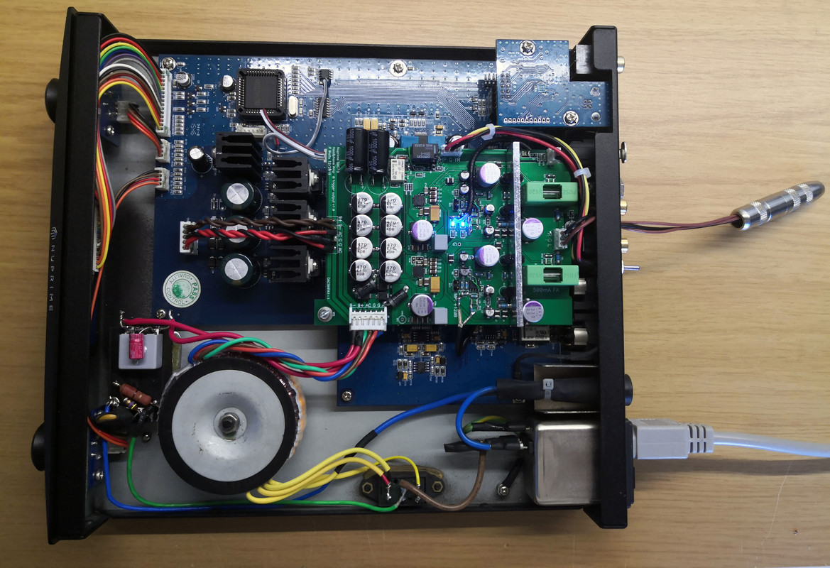
And, below is the full result in its entirety:
Overall, I'm very happy with the result. The unit still has all its original functionality (perhaps even a little better), is much better protected and now has the additional features I wanted. The headphone circuit is dead-quiet and sounds great. Visually the wiring and mechanics could definitely have been better had I had access to my usual tools at work, but overall I'm quite pleased with the result.