So I got hold of a Cambridge Audio Azure 640A V2.0 amplifier a while back and thought it would be a great upgrade for my NAD3150. It had an issue, which thanks to lockdown and a wee bit more free time, I managed to sort out. The only problem vs the current setup: no integrated phono?
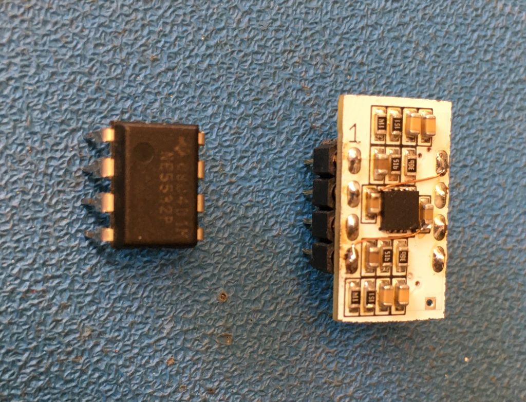
Options? Buy a phono stage or make one? I then read all the various posts on the forum from other members wanting to do their own and decided to go for my own build of the Muffsy. Mine would be a tad different though. The 640A has buffered inputs, so I thought to use this to my advantage and have an internal phono stage that uses the AUX input buffer as the insertion point. The reason for using the AUX input is that the remote control button is labelled AUX/PHONO. Though I fail to see the use of a remote to change inputs when one has to get up and put on a record anyway. The concept was NE5532 out, phono stage in? plenty of space available in the amp.
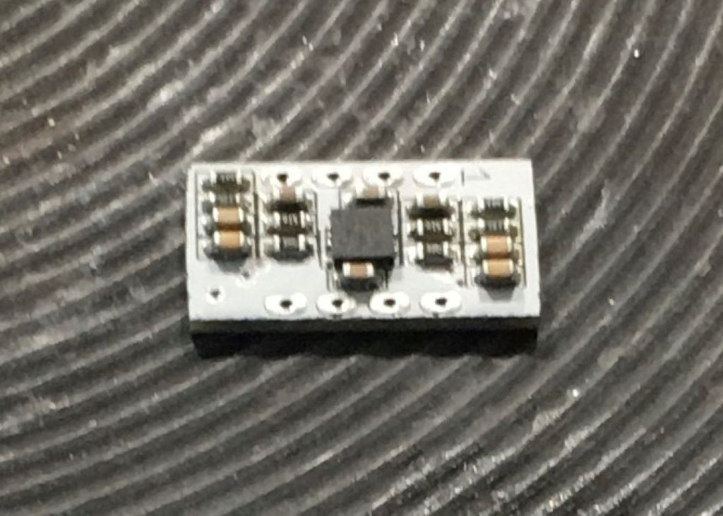
The Muffsy schematic was entered into the CAD system, but I then thought: ?Why not make it smaller and simpler?? So I did. After a bit of toying around and pondering, I left out all the input impedance and output gain switching options. Yes, I went all out! Because I could! Double-sided component placement, and SHOCK HORROR using ceramic capacitors in the RIAA audio path to miniaturise as much as possible. The idea here was to go tiny, so the use of poly caps was not really an option. I managed to get 5% tolerance capacitors, so hopefully they'll perform OK. Listening will tell if the ceramic capacitors are good enough! I also found a decent audio op amp from Texas Instruments, OPA1678, not top-notch, but good for the price I wanted to pay. Teeny, 3mm X 3mm. It?s a FET input, as Muffsy recommends for a MM cartridge.
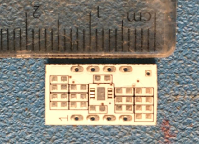
There was a small area on one of my work PCBs that was being cut out and not being used in the final product. I took advantage of it and placed a few phono boards in the space. It?s an LED board, hence the white soldermask?
Nice and small!!
Solder paste was applied to the pads and then populated the components themselves. The components are 0603 size, or 1608 in metric terms ? 1.6mm X 0.8mm. Top layer components placed on board and being ?cooked?. Yes, I use a solid plate electric stove-top to do most of my SMD soldering, by far the easiest and quickest method. Just takes a few goes to get to know the best temperature setting for the type of board. We use a lot of aluminium substrate PCBs and this is the only way to reliably solder a hand-build or to fix them.
(Apologies for lack of focus)
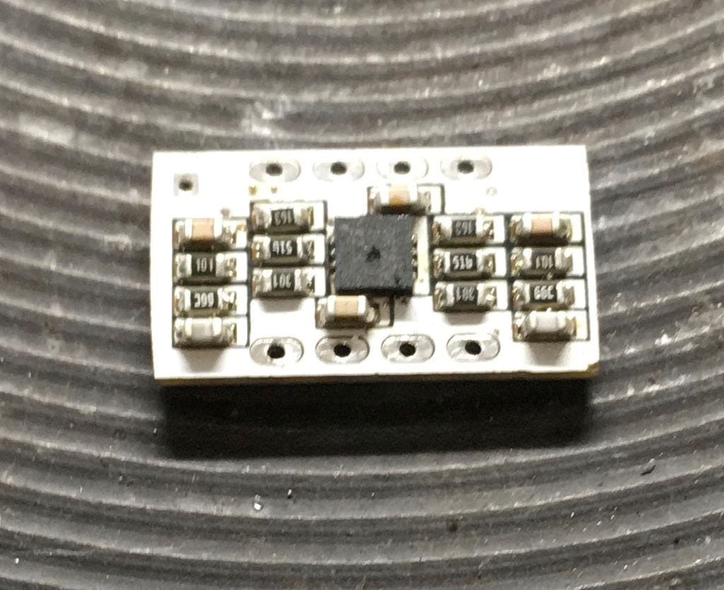
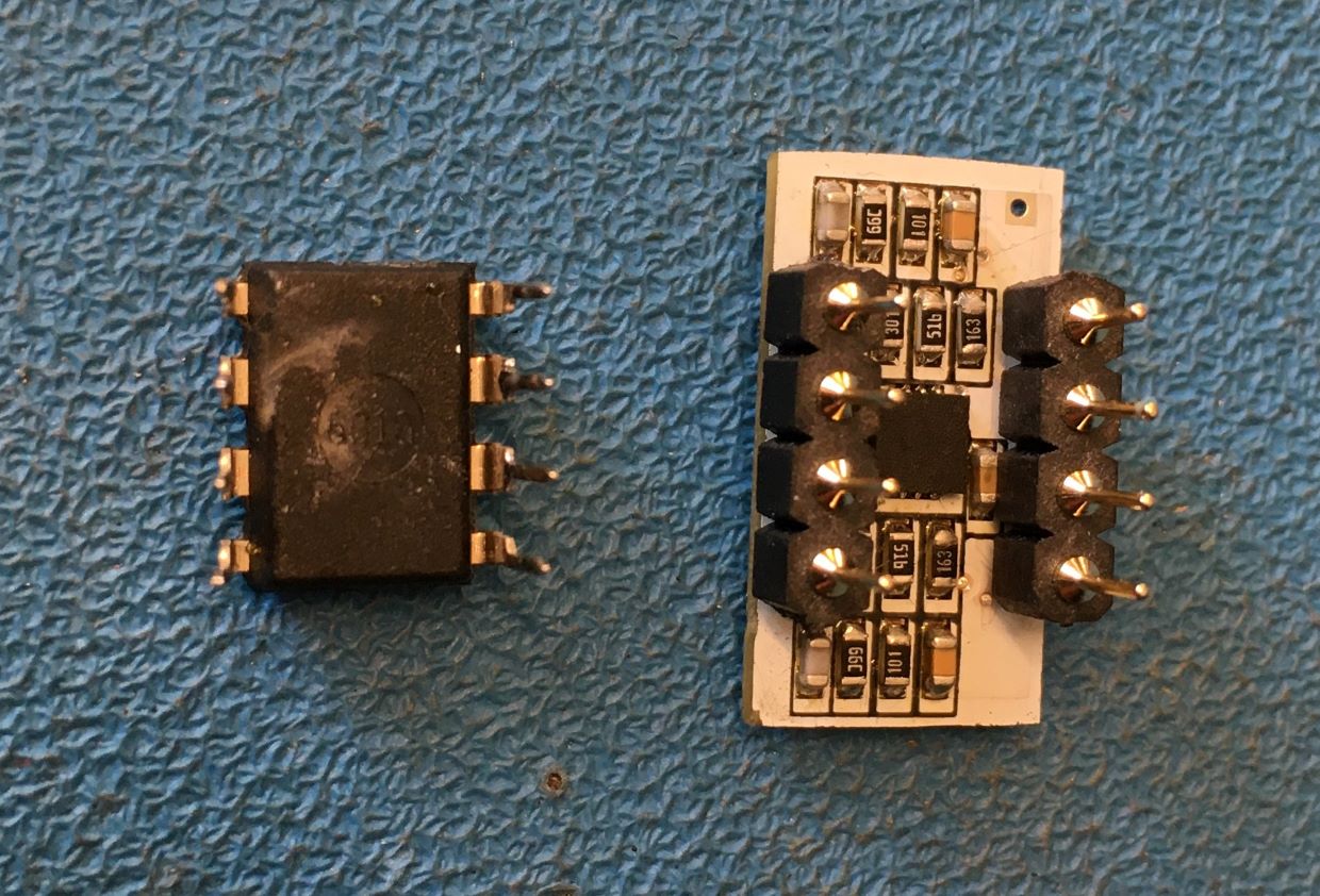
Repeat with bottom side components:
The idea was to get the phono stage to match the buffer chip footprint, so that it all fits in a space just a little larger than the 5532. Some SIL pins were soldered in place and almost ready to go! Power traces had to be wired with transformer wire (my favourite wire to use for mods or minor repairs) as the routing on the PCB was just too tight?
Top side with 5532 next to it:
Bottom side:
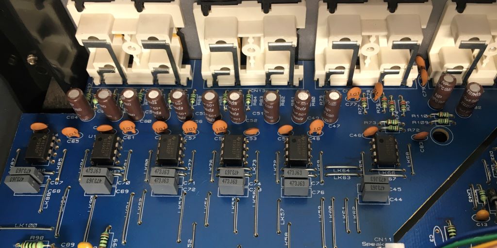
The buffer chip needed to be removed and a socket put in its place for the phono stage. Fortunately the AUX input is closest to the side of the amp PCB, as the Cambridge is not as maintenance-friendly as for instance the NAD amps, where the whole bottom cover can be removed.
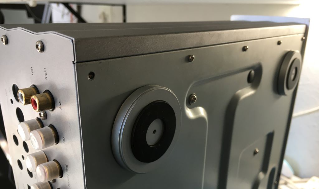
Turned out to be not such a problem after all! The side panel comes off easily and everything is quite accessible.
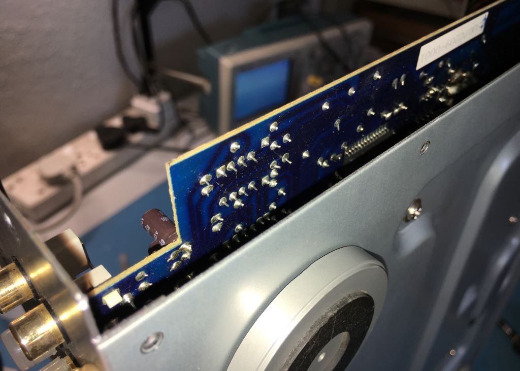
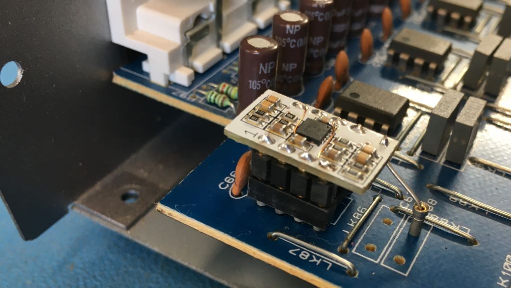
So 5532 was removed, socket soldered in place, and phono stage inserted. One issue with the direct footprint approach was the lack of a ground signal on any of the pins, with the power to the op amp being +15V and -15V. The power decoupling capacitors were removed, as there are some on the phono PCB and a fly lead was used from the ground connection on the main PCB to the phono PCB. It doesn?t look as neat, but unavoidable unfortunately.
New-look inputs!
Well, mission accomplished! The inputs on this amp are already terminated with 47kohm and 100pF to ground, so those options were left unpopulated on the phono PCB (actually removed after photos were taken?). The gain was set at 37,9dB, which seems fine after having listened for a while now.
It might not be audiophile, as there is a slight hum and hiss at zero input, volume half. I put this down to ground and power routing on the tiny PCB which is far from ideal. Am I happy with it? Yes. I can now listen to vinyl on my lowly Thorens TD-150 (with AT-95e) through the cleaner sounding Cambridge Audio 640 without even more clutter next to the amp.
I have rehashed the PCB using even smaller 0402 (1mm X 0,5mm) components to make space for the power routing, but will it be worth making? Not sure? I?m going to try and sort out the noise on the current one first. I will also try and squeeze some poly caps onto the current board and see if it does indeed sound better. Or make up options with various input impedances and gains, so that I can ?Phono-roll?.
But who knows, I might just end up with a separate phono amp eventually, in which case I?ll remove the phono stage and plug the 5532 back in. For now it's a very satisfactory stop-gap.
Options? Buy a phono stage or make one? I then read all the various posts on the forum from other members wanting to do their own and decided to go for my own build of the Muffsy. Mine would be a tad different though. The 640A has buffered inputs, so I thought to use this to my advantage and have an internal phono stage that uses the AUX input buffer as the insertion point. The reason for using the AUX input is that the remote control button is labelled AUX/PHONO. Though I fail to see the use of a remote to change inputs when one has to get up and put on a record anyway. The concept was NE5532 out, phono stage in? plenty of space available in the amp.
The Muffsy schematic was entered into the CAD system, but I then thought: ?Why not make it smaller and simpler?? So I did. After a bit of toying around and pondering, I left out all the input impedance and output gain switching options. Yes, I went all out! Because I could! Double-sided component placement, and SHOCK HORROR using ceramic capacitors in the RIAA audio path to miniaturise as much as possible. The idea here was to go tiny, so the use of poly caps was not really an option. I managed to get 5% tolerance capacitors, so hopefully they'll perform OK. Listening will tell if the ceramic capacitors are good enough! I also found a decent audio op amp from Texas Instruments, OPA1678, not top-notch, but good for the price I wanted to pay. Teeny, 3mm X 3mm. It?s a FET input, as Muffsy recommends for a MM cartridge.
There was a small area on one of my work PCBs that was being cut out and not being used in the final product. I took advantage of it and placed a few phono boards in the space. It?s an LED board, hence the white soldermask?
Nice and small!!
Solder paste was applied to the pads and then populated the components themselves. The components are 0603 size, or 1608 in metric terms ? 1.6mm X 0.8mm. Top layer components placed on board and being ?cooked?. Yes, I use a solid plate electric stove-top to do most of my SMD soldering, by far the easiest and quickest method. Just takes a few goes to get to know the best temperature setting for the type of board. We use a lot of aluminium substrate PCBs and this is the only way to reliably solder a hand-build or to fix them.
(Apologies for lack of focus)
Repeat with bottom side components:
The idea was to get the phono stage to match the buffer chip footprint, so that it all fits in a space just a little larger than the 5532. Some SIL pins were soldered in place and almost ready to go! Power traces had to be wired with transformer wire (my favourite wire to use for mods or minor repairs) as the routing on the PCB was just too tight?
Top side with 5532 next to it:
Bottom side:
The buffer chip needed to be removed and a socket put in its place for the phono stage. Fortunately the AUX input is closest to the side of the amp PCB, as the Cambridge is not as maintenance-friendly as for instance the NAD amps, where the whole bottom cover can be removed.
Turned out to be not such a problem after all! The side panel comes off easily and everything is quite accessible.
So 5532 was removed, socket soldered in place, and phono stage inserted. One issue with the direct footprint approach was the lack of a ground signal on any of the pins, with the power to the op amp being +15V and -15V. The power decoupling capacitors were removed, as there are some on the phono PCB and a fly lead was used from the ground connection on the main PCB to the phono PCB. It doesn?t look as neat, but unavoidable unfortunately.
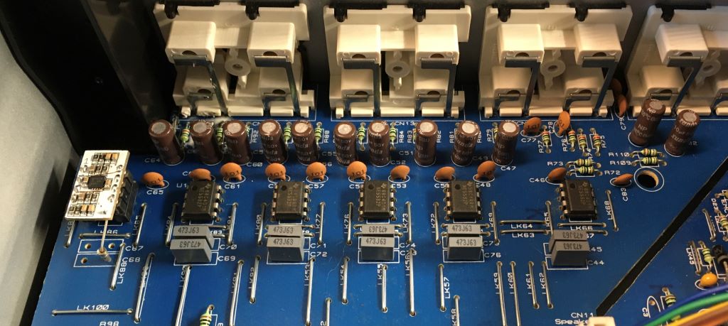
New-look inputs!
Well, mission accomplished! The inputs on this amp are already terminated with 47kohm and 100pF to ground, so those options were left unpopulated on the phono PCB (actually removed after photos were taken?). The gain was set at 37,9dB, which seems fine after having listened for a while now.
It might not be audiophile, as there is a slight hum and hiss at zero input, volume half. I put this down to ground and power routing on the tiny PCB which is far from ideal. Am I happy with it? Yes. I can now listen to vinyl on my lowly Thorens TD-150 (with AT-95e) through the cleaner sounding Cambridge Audio 640 without even more clutter next to the amp.
I have rehashed the PCB using even smaller 0402 (1mm X 0,5mm) components to make space for the power routing, but will it be worth making? Not sure? I?m going to try and sort out the noise on the current one first. I will also try and squeeze some poly caps onto the current board and see if it does indeed sound better. Or make up options with various input impedances and gains, so that I can ?Phono-roll?.
But who knows, I might just end up with a separate phono amp eventually, in which case I?ll remove the phono stage and plug the 5532 back in. For now it's a very satisfactory stop-gap.