Following up on the streamer, I reused much of the same stuff to build a proper external linear PSU for a Mutec MC3 USB I hounded [member=13375]Jessejon[/member] to sell to me.
I saw online that many folks were doing this with good results and thought why not do the same as a spinoff from the streamer project.
First off we have the power supply itself. This is basically a copy of the streamer using the same AC input filter & trigger IOs etc. but with a discrete 50VA toroid shoe-horned in instead of the 25VA PCB-mount versions since this one actually has to deliver some real power. Similarly the inductors were removed to reduce losses but there's ample filtering. Regulated output voltage is 6.3VDC, same as with the stock unit. Chassis is the same concept, a custom powder-coated folded steel business.
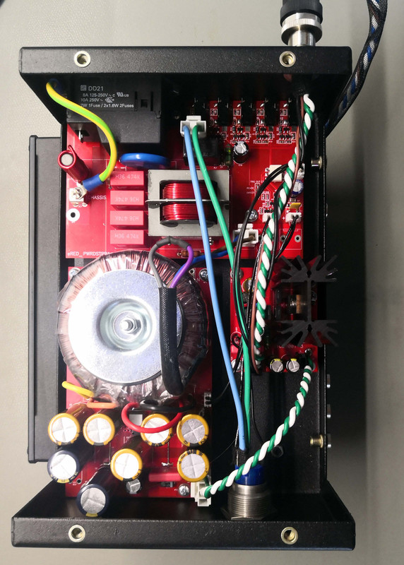
The regulator is again based on the Studer 900 concept used earlier, but is actually a different design with a separate set of sense wires to correct for losses on the cable. The connector is a very sturdy industrial type that has a very strong screw-in locking function. Cables are oversized & once again a quality silver-coated OFC with Teflon. The sensing wires are tightly wrapped around the power supply wires since noise pickup on them can lead to instability. Everything got wrapped in braid for a nice finished look.
First prize would have been to place the regulator inside the Mutec, but the heat dissipation would be too high to make it fit but with a short & thick cable and remote sense it should come VERY close.
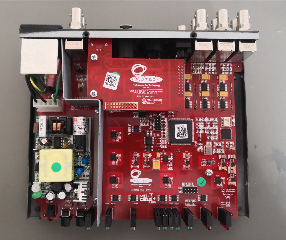
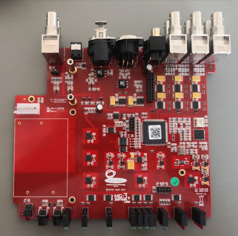
Next up was modifying the stock Mutec unit. Most modders just removed the switching supply and hard-soldered a wire to the pads but that's so boorish. Below is the stock unit, with the green board being the stock AC-DC power supply and the next image after it has been carefully removed.
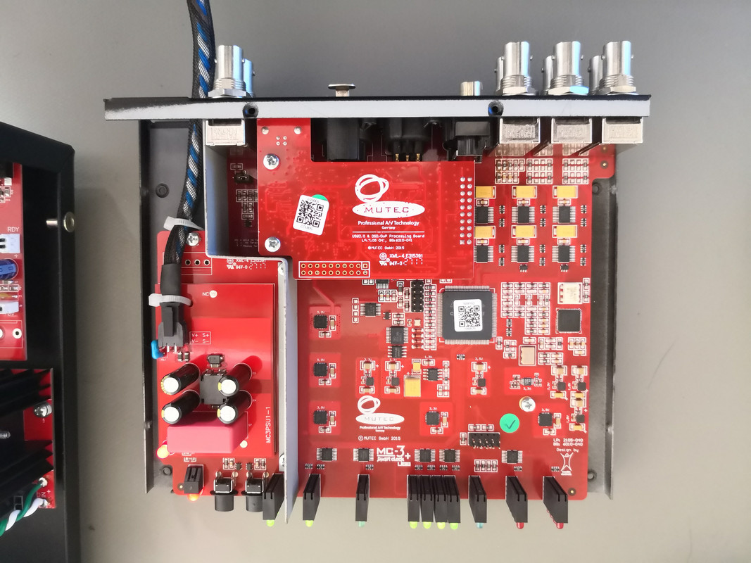
My take was to have a little PCB made with identical size and pins of the original power supply, and a removable locking connector. This is just a passive module, but is where the sensing wires join the power connection and also does a healthy amount of common & differential-mode filtering and spike suppression. Capacitance was deliberately kept modest since the regulator is designed to use low load capacitance. A 1uF MKP cap does the final filtering before entering the actual load.
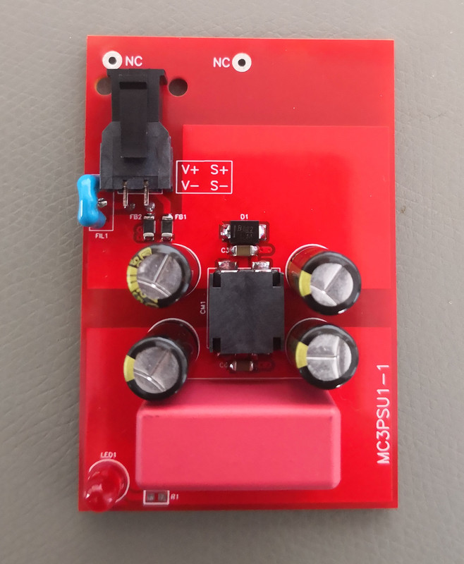
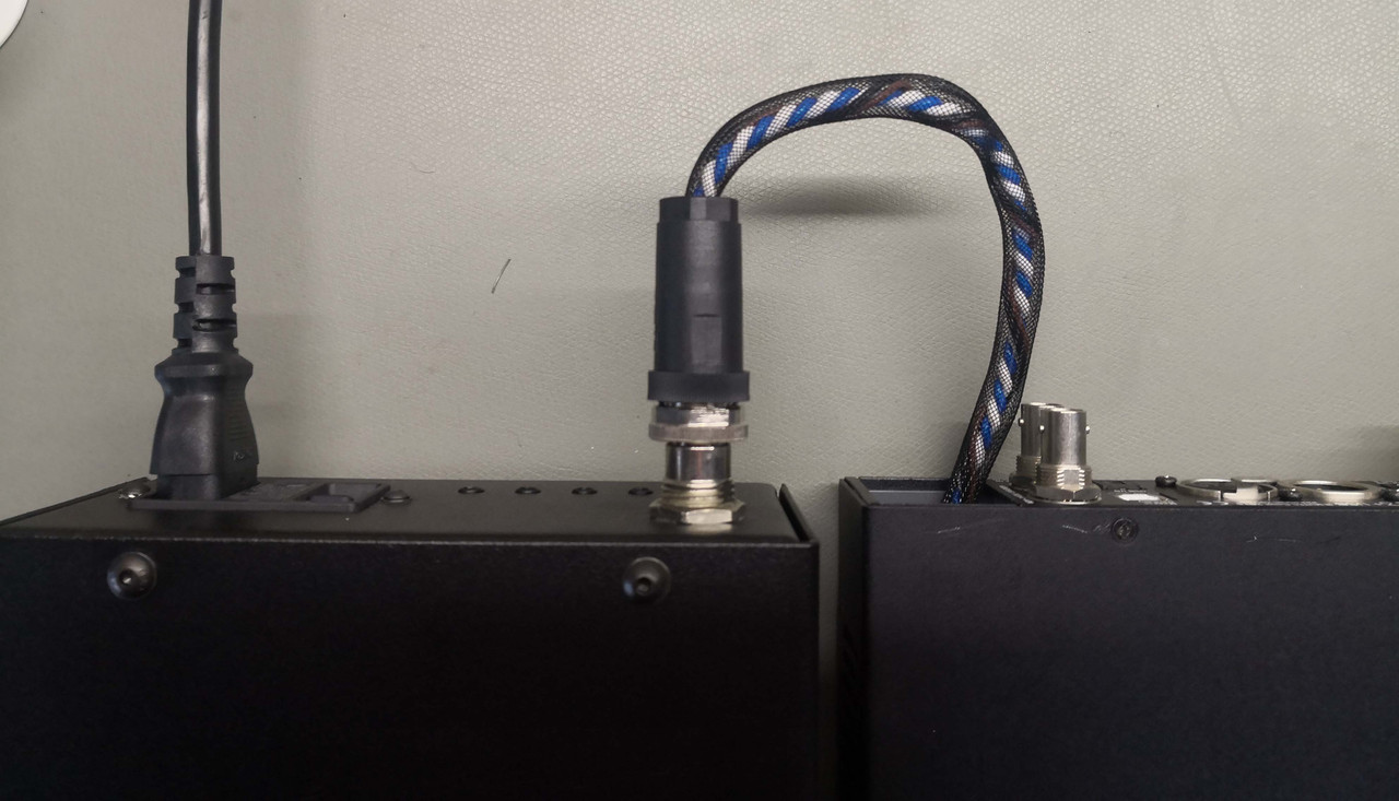
Below is the module mounted and showing the cabled connection.
I kept the umblical cord as short as possible since the intention is to keep the power supply right next to the unit.
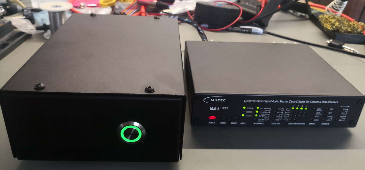
Lastly, the final product. Once again, a front-panel power switch has a bicolour LED that is red when the output voltage has not stabilized and green when it has.
Overall, a success again. The sensing circuit works exactly as it should, with the output at the source being a few mV higher than at the load but the load voltage being the target value.
The PSU does get hot, but it has an ample heatsink and ventilation slots. Performance I'm not sure of, but it sounds sublime and once again the power supply measures far cleaner than with the original switcher. Once again, cosmetics can improve with a nice thick faceplate. The PSU mod is fully reversible if needed, but besides the 4W or so extra power consumption and size I can't see why.
I saw online that many folks were doing this with good results and thought why not do the same as a spinoff from the streamer project.
First off we have the power supply itself. This is basically a copy of the streamer using the same AC input filter & trigger IOs etc. but with a discrete 50VA toroid shoe-horned in instead of the 25VA PCB-mount versions since this one actually has to deliver some real power. Similarly the inductors were removed to reduce losses but there's ample filtering. Regulated output voltage is 6.3VDC, same as with the stock unit. Chassis is the same concept, a custom powder-coated folded steel business.
The regulator is again based on the Studer 900 concept used earlier, but is actually a different design with a separate set of sense wires to correct for losses on the cable. The connector is a very sturdy industrial type that has a very strong screw-in locking function. Cables are oversized & once again a quality silver-coated OFC with Teflon. The sensing wires are tightly wrapped around the power supply wires since noise pickup on them can lead to instability. Everything got wrapped in braid for a nice finished look.
First prize would have been to place the regulator inside the Mutec, but the heat dissipation would be too high to make it fit but with a short & thick cable and remote sense it should come VERY close.
Next up was modifying the stock Mutec unit. Most modders just removed the switching supply and hard-soldered a wire to the pads but that's so boorish. Below is the stock unit, with the green board being the stock AC-DC power supply and the next image after it has been carefully removed.
My take was to have a little PCB made with identical size and pins of the original power supply, and a removable locking connector. This is just a passive module, but is where the sensing wires join the power connection and also does a healthy amount of common & differential-mode filtering and spike suppression. Capacitance was deliberately kept modest since the regulator is designed to use low load capacitance. A 1uF MKP cap does the final filtering before entering the actual load.
Below is the module mounted and showing the cabled connection.
I kept the umblical cord as short as possible since the intention is to keep the power supply right next to the unit.
Lastly, the final product. Once again, a front-panel power switch has a bicolour LED that is red when the output voltage has not stabilized and green when it has.
Overall, a success again. The sensing circuit works exactly as it should, with the output at the source being a few mV higher than at the load but the load voltage being the target value.
The PSU does get hot, but it has an ample heatsink and ventilation slots. Performance I'm not sure of, but it sounds sublime and once again the power supply measures far cleaner than with the original switcher. Once again, cosmetics can improve with a nice thick faceplate. The PSU mod is fully reversible if needed, but besides the 4W or so extra power consumption and size I can't see why.