Here is a bit of eye candy for those who like the dusty insides of a tube amplifier. I find analysing circuits from the tube era informative, because it might reveal the reasoning behind the design; a reasoning one can apply to your own projects.
Here is the amplifier I am going to restore:
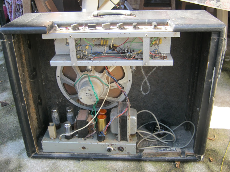
As you can see, it is an EL34 push-pull amplifier with a GZ34 rectifier. The PP amp is cathode biased with a shared resistor.
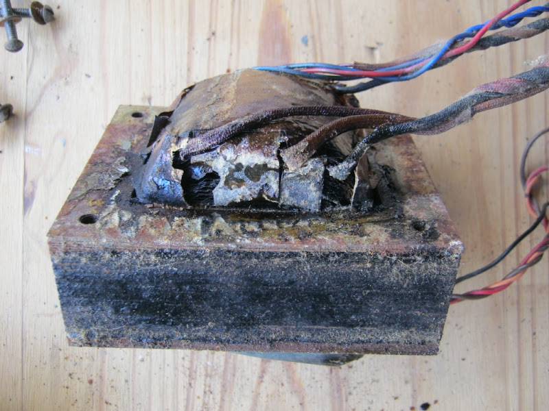
The power amplifier on the base of the cabinet is tripping the switch at the switch board, so somewhere there must be a short circuit to earth. As it turns out, the power transformer is literally toast. I was curious to find out what voltages the transformer put out when it was working; something I cannot measure now.
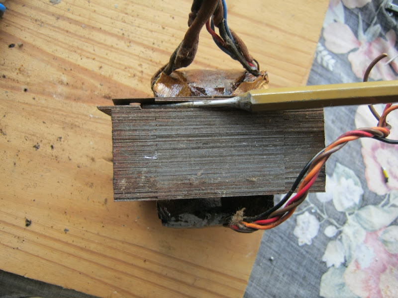
I took the transformer off the chassis and started stripping it.
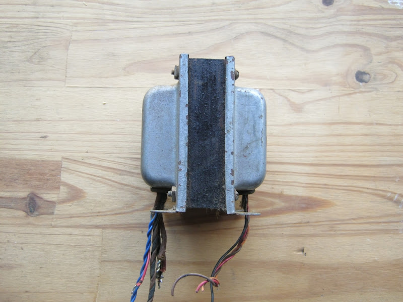
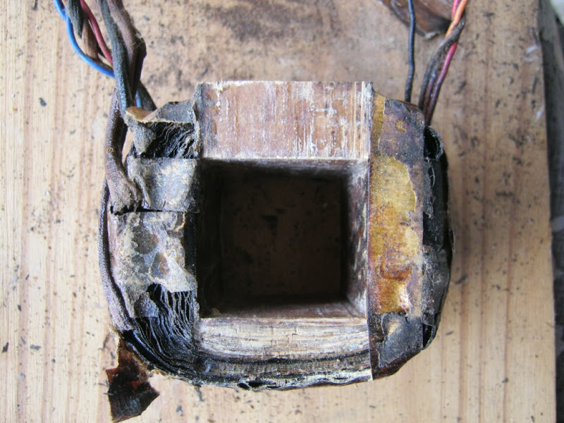
You can see tha the stack, with the covers on, measures just over 40mm's. The stack without the covers is 38mm's high. It is very common to design transformers with square cores. This one uses EI114 laminations and they have a 38mm tongue. Dimension A in the drawing below.

Inside the transformer looks rusted and it is probably time that a new one is fitted anyway
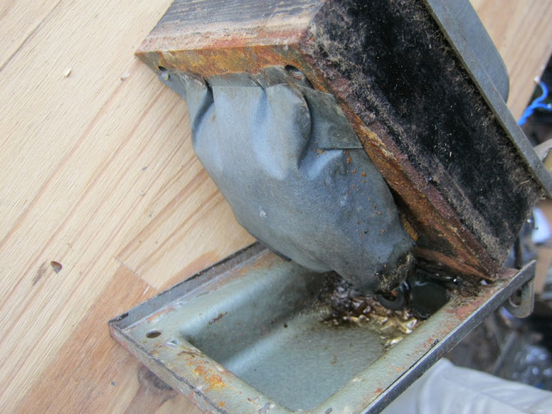
A protective covering was fitted over the wires to prevent wires chafing through and shorting to the metalcovers
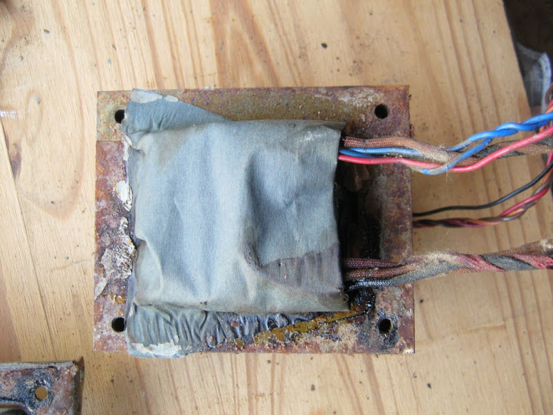
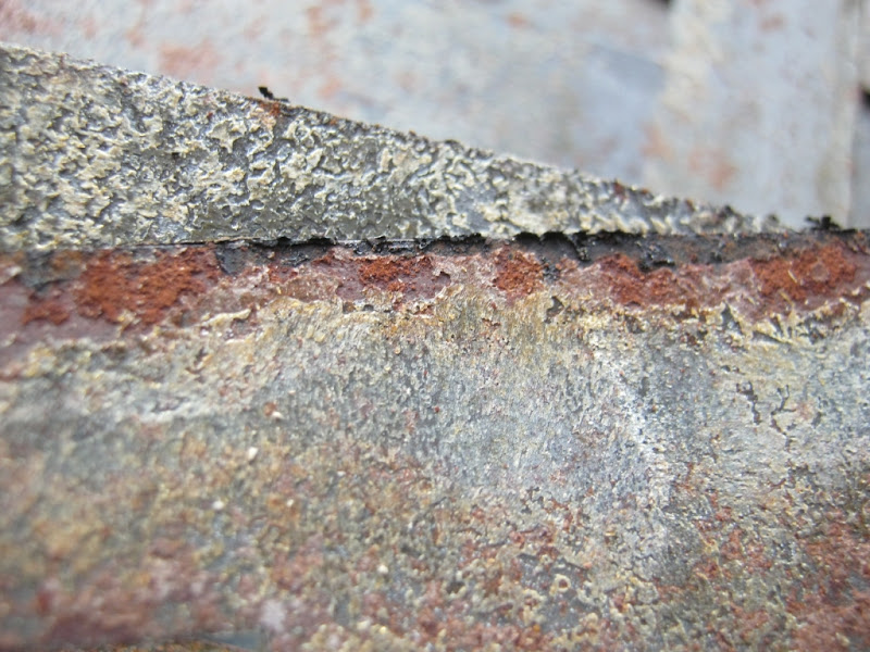
The transformers shows beautiful textures
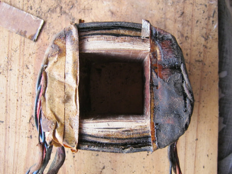
First I took out the laminations
I rust not beautiful?
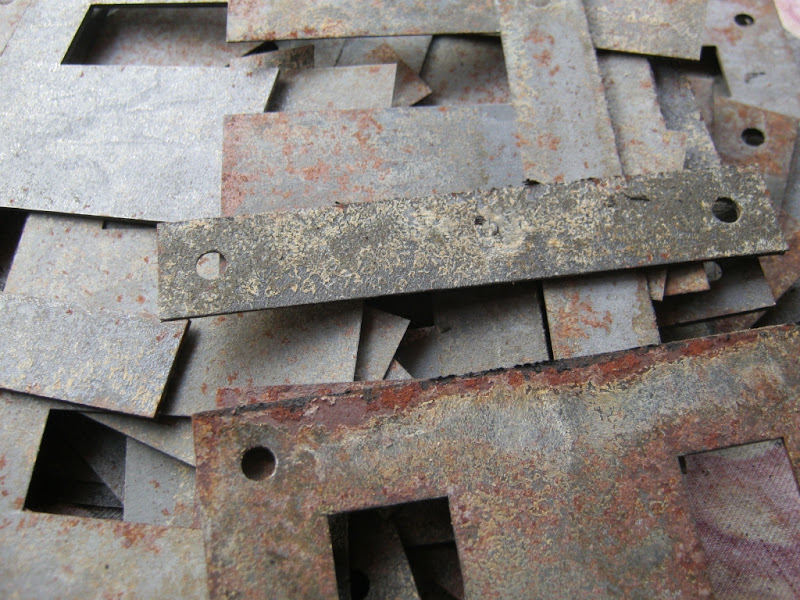
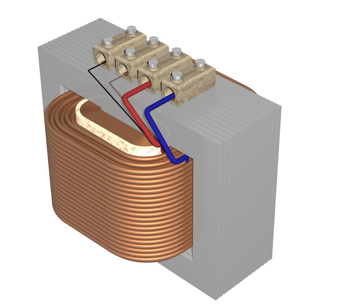
Laminations out, and the bobbin becomes accessible to our prying eyes
Primary on the inside and secondary on the outside like this
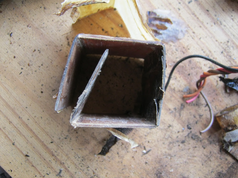
The bobbin former was easy to remove, so I did that
I could reach the primary windings, and measured the diameter of the copper wire
I guess the diameter should be 0.6mm, since there is a bit dirt on the wire, making it read slightly over 0.6mm
I could pull out a bit of secondary to measure
I guess that should be 0.3mm wire
The rectifier filament winding reads 1.14mm
and the tube heaters (6.3V secondary) 1.5mm
Next I measured the primary winding DC resistance
Brown wire
Red wire
Orange wire
Next the high tension secondary. There are three wires, with Red the centre tap:
From center to one brown wire:
and the other brown wire
Those two should be more or less equal. The 24 ohm reading indicates a short circuit somewhere inside
Off to Yves's Power Transformer designer to see if I can reconstruct the transformer:
I chose a 38x38mm bobbin
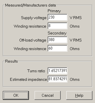
I started with the high tension AC at 360V, but had to up it to 380V to get the right DC resistance to match what I measured on the old transformer, namely 60 ohms. I also started with a 0.2A current rating for the HT winding, but had to down scale it to 0.18A to bring total heat losses in the copper to the preferred design value of 10%. (See section 2 and 3 current rating and 10.7% rating on orange block, at the bottom)
The flux was adjusted to 1.2 Tesla, a very common design choice for NOSS laminations. The resistances came out very close to the measured ones. Let us simulate the transformer in the cicruit.
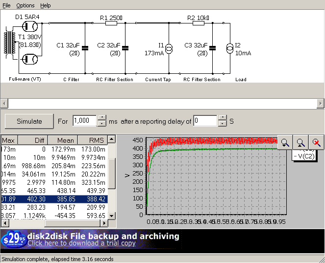
I opened Duncanamps's PSU designer and entered the data
(other details like resistor and capacitor values I got from visual inspection of the circuit.:
I checked the outcome with the published data:
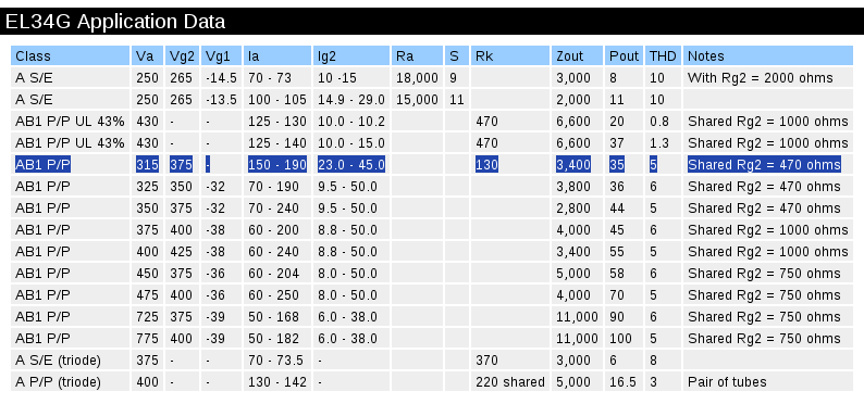
You can see that the original builder of the amplifier probably used the same data sheet as we have before us. At idle the amplifier consumes 150mA anode current and 23mA screen current, very close to our guess of 180mA. I could also see the shared 470 ohm resistor on the actual amplifier.
Now I can manufacture a replacement that should be perfect for the amplifier.
Here is the amplifier I am going to restore:
As you can see, it is an EL34 push-pull amplifier with a GZ34 rectifier. The PP amp is cathode biased with a shared resistor.
The power amplifier on the base of the cabinet is tripping the switch at the switch board, so somewhere there must be a short circuit to earth. As it turns out, the power transformer is literally toast. I was curious to find out what voltages the transformer put out when it was working; something I cannot measure now.
I took the transformer off the chassis and started stripping it.
You can see tha the stack, with the covers on, measures just over 40mm's. The stack without the covers is 38mm's high. It is very common to design transformers with square cores. This one uses EI114 laminations and they have a 38mm tongue. Dimension A in the drawing below.
Inside the transformer looks rusted and it is probably time that a new one is fitted anyway
A protective covering was fitted over the wires to prevent wires chafing through and shorting to the metalcovers
The transformers shows beautiful textures
First I took out the laminations
I rust not beautiful?
Laminations out, and the bobbin becomes accessible to our prying eyes
Primary on the inside and secondary on the outside like this
The bobbin former was easy to remove, so I did that
I could reach the primary windings, and measured the diameter of the copper wire
I guess the diameter should be 0.6mm, since there is a bit dirt on the wire, making it read slightly over 0.6mm
I could pull out a bit of secondary to measure
I guess that should be 0.3mm wire
The rectifier filament winding reads 1.14mm
and the tube heaters (6.3V secondary) 1.5mm
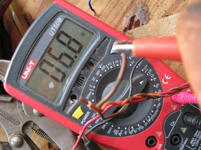
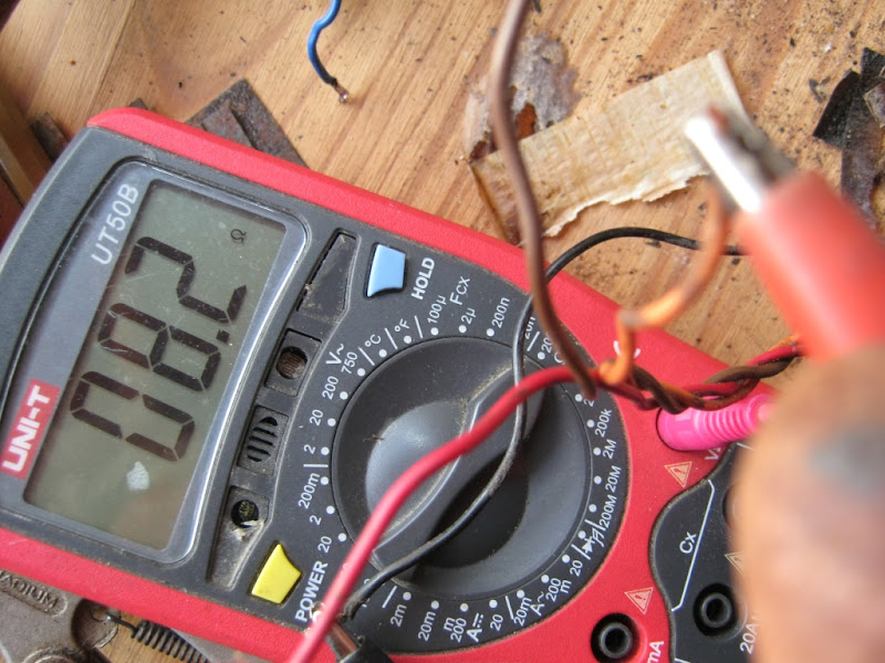
Next I measured the primary winding DC resistance
Brown wire
Red wire
Orange wire
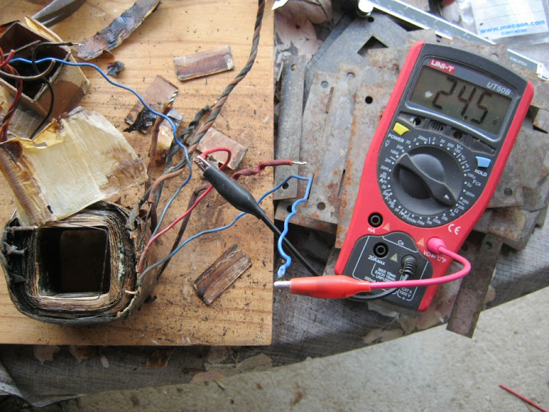
Next the high tension secondary. There are three wires, with Red the centre tap:
From center to one brown wire:
and the other brown wire
Those two should be more or less equal. The 24 ohm reading indicates a short circuit somewhere inside
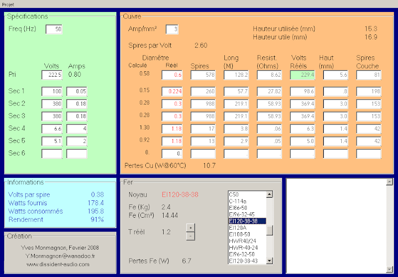
Off to Yves's Power Transformer designer to see if I can reconstruct the transformer:
I chose a 38x38mm bobbin
I started with the high tension AC at 360V, but had to up it to 380V to get the right DC resistance to match what I measured on the old transformer, namely 60 ohms. I also started with a 0.2A current rating for the HT winding, but had to down scale it to 0.18A to bring total heat losses in the copper to the preferred design value of 10%. (See section 2 and 3 current rating and 10.7% rating on orange block, at the bottom)
The flux was adjusted to 1.2 Tesla, a very common design choice for NOSS laminations. The resistances came out very close to the measured ones. Let us simulate the transformer in the cicruit.
I opened Duncanamps's PSU designer and entered the data
(other details like resistor and capacitor values I got from visual inspection of the circuit.:
I checked the outcome with the published data:
You can see that the original builder of the amplifier probably used the same data sheet as we have before us. At idle the amplifier consumes 150mA anode current and 23mA screen current, very close to our guess of 180mA. I could also see the shared 470 ohm resistor on the actual amplifier.
Now I can manufacture a replacement that should be perfect for the amplifier.