While I have a myriad of other projects to attend to, our mates in the underworld of energy supply is forcing my hand a bit ... 
It is time to complete the hybrid system I designed and started installing over the last two years.
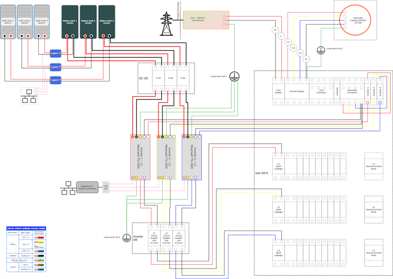
As things are, the original design was based on obtaining energy from a three phase generator that can burn most anything oily and a 12V bank of Aluminium Air cells I designed and built the protoype of. This battery is not completed (due to various failed immigration reasons) so I need to find a quick second option. My choice here being LiFeSO4 battery bank.
I therefore have to adjust the design a little bit to allow me to keep working and obviously not disturb the neighbours too much with a thumbing generator.
Two years ago I did a energy calculation for the electrical equipment as found in the house and office. Part of the exercise was to replace most everything with A++ energy rated equipment. The second step was to split the house's wiring system into four circuits. The first being things that draw a lot of power such as the oven, the lathe and most of my power tools. The remainder then into three circuits being L1, L2 and L3 of a three phase supply from the generator. Each circuit then supplied by its own 1,5kW sine wave inverter which can draw electricity from a selected source, such as grid, genset, batteries, solar or in future the Alu Air battery bank.
This exercise took about three months of my time to rewire the whole house and my garage (read man cave). Part of this was splitting the old DB into three new DBs and each DB into the four circuits to be supplied.
Due to the technology advances, there are numerous options regarding solar banks, MPPT chargers, battery charges and batteries and this is requiring of me to change my design a bit. The design I am aiming for now is as per the below layout.
My current adventure is to determine what the LiFeSO4 battery bank must look like, how to charge this and how to montior the whole system from any browser.
The question also is if I must sell the existing inverters and rather buy a new more efficient 3-phase inverter.
If you have been down this rabbit hole and can provide me with some solid advice regarding options I can consider I will greatly appreciate it.
EDIT - Adding SANS 10142-1 requirements
I found the following post that lists the following SANS 10142 requirements pertaining to this type of installation:
So let’s jump in:
[Format will be “Statement” and then a separate ("|") and pointing to clauses (if available)
So, if you are doing installs or getting a sparky to check the installations, please consider the few points above. With the CoCT sign-off by a Pr. Eng requiring the engineer to sign-off on the SANS compliance, it can become a bit sticking point…
EDIT - Adding SANS 10142-1 indication and labeling requirements
There are a number of labels, notices and indicator lamps that needs to be installed as per SANS 10142-1 requirements. Let's start off with an unorganised list.
Indication:
1. Where any form of alternative supply supplies power only to certain circuits in a distribution board, a power-on indicator (visible or audible) shall be provided on each such distribution board. | Clause 7.12.2.1
Labeling:
1.
It is time to complete the hybrid system I designed and started installing over the last two years.
As things are, the original design was based on obtaining energy from a three phase generator that can burn most anything oily and a 12V bank of Aluminium Air cells I designed and built the protoype of. This battery is not completed (due to various failed immigration reasons) so I need to find a quick second option. My choice here being LiFeSO4 battery bank.
I therefore have to adjust the design a little bit to allow me to keep working and obviously not disturb the neighbours too much with a thumbing generator.
Two years ago I did a energy calculation for the electrical equipment as found in the house and office. Part of the exercise was to replace most everything with A++ energy rated equipment. The second step was to split the house's wiring system into four circuits. The first being things that draw a lot of power such as the oven, the lathe and most of my power tools. The remainder then into three circuits being L1, L2 and L3 of a three phase supply from the generator. Each circuit then supplied by its own 1,5kW sine wave inverter which can draw electricity from a selected source, such as grid, genset, batteries, solar or in future the Alu Air battery bank.
This exercise took about three months of my time to rewire the whole house and my garage (read man cave). Part of this was splitting the old DB into three new DBs and each DB into the four circuits to be supplied.
Due to the technology advances, there are numerous options regarding solar banks, MPPT chargers, battery charges and batteries and this is requiring of me to change my design a bit. The design I am aiming for now is as per the below layout.

My current adventure is to determine what the LiFeSO4 battery bank must look like, how to charge this and how to montior the whole system from any browser.
The question also is if I must sell the existing inverters and rather buy a new more efficient 3-phase inverter.
If you have been down this rabbit hole and can provide me with some solid advice regarding options I can consider I will greatly appreciate it.
EDIT - Adding SANS 10142-1 requirements
I found the following post that lists the following SANS 10142 requirements pertaining to this type of installation:
So let’s jump in:
[Format will be “Statement” and then a separate ("|") and pointing to clauses (if available)
- AC and DC conductors shall not be in the same trunking | 6.1.10, 3.85, 6.1.7,6.4.1, good practice
- Protection devices shall be DC rates (see other post, very well explained) | 7.5.1.1
- Correct protection and cable selection for batteries | 7.15.1.1
- All DC cables must be labelled accordingly | Clause 7.12.x somewhere
- The neutral shall not be earthed beyond an earth leakage | 7.16.4.5
- a TN-S system shall not be converted to a TN-C system | 7.16.4.6
- If a system is a hybrid and can operate in island mode, the earth leakage on the plug circuits shall be tested when inverter is islanded. Where applicable a earth-neutral bond (via relay) shall be installed to ensure proper operation of the earth leakage during grid loss events. | Clause 7.12.3
- Notice/Labelling to indicate alternate supply, this includes that all “back-up” circuits be specifically and clearly labelled. | Clause 7.12.2.1
- Alternate supply short circuit current taken into account with main incoming short circuit currents | Clause 7.12.2.3
- Earth Leakage installed after the inverter output | Clause 7.12.2.6
- Correct Surge Protection has been installed on all DC and AC components as required by the lightning risk assessment
- Neutral bar shall be split between council supply and on-site supply | Clause 7.12.3.1.4
- Solar panel frame and structure shall be bonded to the consumer earth | Clause 7.12
- Where single core conductors are used, such conductors for each circuit shall be tied together at intervals to ensure identification, unless another suitable arrangement is employed. | Clause 7.12
- All DC (string cables) to be in conduits or where applicable affixed to the structure (no matter if they are UV rated)
- All DC string cables to be labelled accordingly and voltage levels indicated on both the cable ends and the Distribution board. Note both operating voltage (max) and allowable voltage for the system on the DB board.
- In addition it shall be recognised that the supply from each inverter, battery arrangement and PV panel (or identified clustered group), constitutes a supply, and requires arrangements similar to point of supply, which shall include switch-disconnection arrangements and shall comply with 7.12.5.
- Does the CoC specifically include mention of the Alternative Supply? Has all the appropriate boxes been ticked and the description made specific to in the PV installation?
So, if you are doing installs or getting a sparky to check the installations, please consider the few points above. With the CoCT sign-off by a Pr. Eng requiring the engineer to sign-off on the SANS compliance, it can become a bit sticking point…
EDIT - Adding SANS 10142-1 indication and labeling requirements
There are a number of labels, notices and indicator lamps that needs to be installed as per SANS 10142-1 requirements. Let's start off with an unorganised list.
Indication:
1. Where any form of alternative supply supplies power only to certain circuits in a distribution board, a power-on indicator (visible or audible) shall be provided on each such distribution board. | Clause 7.12.2.1
Labeling:
1.
Last edited: