Here I focus on a prevalent misunderstanding concerning loudspeaker crossover topology and then present a worked example showing a way to do it correctly.
Literature discussing crossover topologies typically reference standardised filter types. This practice is inherited from the Telecommunications field. Filters are characterised by the shape of their respective transfer functions. The selection of a particular filter may be done based on its quality factor (Q), roll-off rate, phase response and also the final response when summed with other filter sections. Common filter types are Butterworth, Chebyshev and Linkwitz-Riley, amongst others. Loudspeaker designs may exploit the same benefits offered by these filters. However, in loudspeakers there is also the consideration of the spatial frequency response (i.e., looking at response off-axis as well as on-axis) and how it is affected by the choice of filter. So far, so good.
But... this is where many speaker builders get it wrong. The most common error novice speaker builders make is to separate filter response from driver frequency response. The correct approach is to think of a loudspeaker as a system. So, then, when we discuss filter choice, we should do so from the point of view of final acoustic response.
F(final) = F(driver) x F(filter)
where F(...) refers to various transfer functions, a.k.a. frequency responses.
If we choose, say, a final response for a tweeter that is characterised as "4th order Linkwitz-Riley, highpass, 2.5kHz", we have the following:
F(final): 4th order Linkwitz-Riley highpass, 2.5kHz (this is the frequency response that the tweeter section of the loudspeaker will produce)
F(driver): frequency response of the driver, as measured in the enclosure (fixed)
F(filter): required filter response (whatever filter sections must be applied ahead of the tweeter to produce an F(final) response).
Tuning a crossover network is greatly simplified by having available an overlay of the target response curves for the respective drivers, to which the processed curves can be graphically matched.
The system targets were as follows:
Bass: -3dB low frequency limit 30Hz; low-pass 200Hz Linkwitz-Riley 4th order (grey)
Midrange: band-pass symmetrical Linkwitz-Riley 4th order; 200Hz/2300Hz (dark green)
Tweeter: high-pass 2300Hz Linkwitz-Riley 4th order (peach)
Figure 6 shows the targets and raw (unprocessed) driver responses.

For this exercise, I’ll show how the midrange's desired response was achieved. The approach is to first apply equalisation to flatten the driver's frequency response, then to apply the appropriate high-pass/low-pass filters.
Figure 7 shows the midrange driver's response, unequalised (light green) and the target response (dark green) LR4, 200Hz/2300Hz.
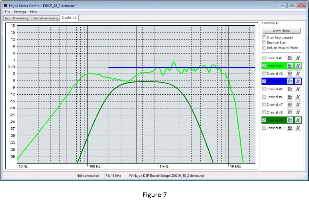
Figure 8 shows the response flattened after applying equalisation.
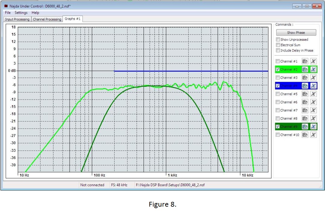
Figure 9 shows the final response after applying 24dB/octave L-R low-pass @ 2300Hz and 24dB/octave L-R high-pass @ 190Hz filters. Note the very good tracking of final response with target response. Reminder that we defined F(final) for the midrange elemement as "band-pass symmetrical Linkwitz-Riley 4th order; 200Hz/2300Hz" ("4th order" is another was of saying "24dB/octave"). We have indeed used two "LR4" filters but only after applying some equalisation. Note, as well, that - even then - one of the LR4 filters is not at the target frequency (190Hz vs 200Hz). It is evident that the filters used are not exactly the same as that which describes the target response.
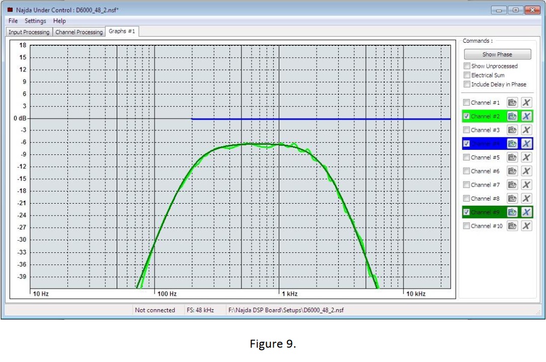
Figure 10 shows the total filter response (purple trace) applied to the driver in order to align it to the target response. Thus:
F(target): dark green
F(final): light green
F(filter): purple
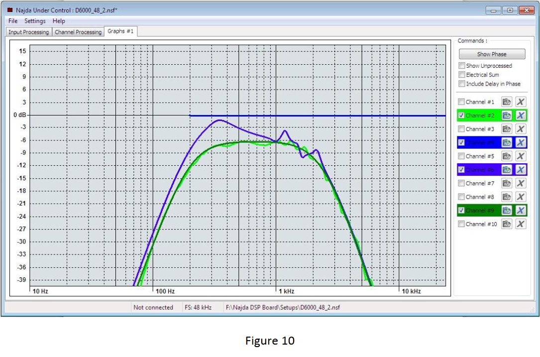
Result:
1. We achieved the target response (BP, LR4, 200Hz/2300Hz).
2. The filter transfer function we developed does not match any "textbook" Linkwitz-Riley alignment. To achieve the target response we used a combination of appropriately chosen equalisation and standard filters.
Literature discussing crossover topologies typically reference standardised filter types. This practice is inherited from the Telecommunications field. Filters are characterised by the shape of their respective transfer functions. The selection of a particular filter may be done based on its quality factor (Q), roll-off rate, phase response and also the final response when summed with other filter sections. Common filter types are Butterworth, Chebyshev and Linkwitz-Riley, amongst others. Loudspeaker designs may exploit the same benefits offered by these filters. However, in loudspeakers there is also the consideration of the spatial frequency response (i.e., looking at response off-axis as well as on-axis) and how it is affected by the choice of filter. So far, so good.
But... this is where many speaker builders get it wrong. The most common error novice speaker builders make is to separate filter response from driver frequency response. The correct approach is to think of a loudspeaker as a system. So, then, when we discuss filter choice, we should do so from the point of view of final acoustic response.
F(final) = F(driver) x F(filter)
where F(...) refers to various transfer functions, a.k.a. frequency responses.
If we choose, say, a final response for a tweeter that is characterised as "4th order Linkwitz-Riley, highpass, 2.5kHz", we have the following:
F(final): 4th order Linkwitz-Riley highpass, 2.5kHz (this is the frequency response that the tweeter section of the loudspeaker will produce)
F(driver): frequency response of the driver, as measured in the enclosure (fixed)
F(filter): required filter response (whatever filter sections must be applied ahead of the tweeter to produce an F(final) response).
Tuning a crossover network is greatly simplified by having available an overlay of the target response curves for the respective drivers, to which the processed curves can be graphically matched.
The system targets were as follows:
Bass: -3dB low frequency limit 30Hz; low-pass 200Hz Linkwitz-Riley 4th order (grey)
Midrange: band-pass symmetrical Linkwitz-Riley 4th order; 200Hz/2300Hz (dark green)
Tweeter: high-pass 2300Hz Linkwitz-Riley 4th order (peach)
Figure 6 shows the targets and raw (unprocessed) driver responses.
For this exercise, I’ll show how the midrange's desired response was achieved. The approach is to first apply equalisation to flatten the driver's frequency response, then to apply the appropriate high-pass/low-pass filters.
Figure 7 shows the midrange driver's response, unequalised (light green) and the target response (dark green) LR4, 200Hz/2300Hz.
Figure 8 shows the response flattened after applying equalisation.
Figure 9 shows the final response after applying 24dB/octave L-R low-pass @ 2300Hz and 24dB/octave L-R high-pass @ 190Hz filters. Note the very good tracking of final response with target response. Reminder that we defined F(final) for the midrange elemement as "band-pass symmetrical Linkwitz-Riley 4th order; 200Hz/2300Hz" ("4th order" is another was of saying "24dB/octave"). We have indeed used two "LR4" filters but only after applying some equalisation. Note, as well, that - even then - one of the LR4 filters is not at the target frequency (190Hz vs 200Hz). It is evident that the filters used are not exactly the same as that which describes the target response.
Figure 10 shows the total filter response (purple trace) applied to the driver in order to align it to the target response. Thus:
F(target): dark green
F(final): light green
F(filter): purple
Result:
1. We achieved the target response (BP, LR4, 200Hz/2300Hz).
2. The filter transfer function we developed does not match any "textbook" Linkwitz-Riley alignment. To achieve the target response we used a combination of appropriately chosen equalisation and standard filters.