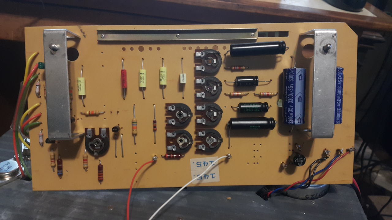
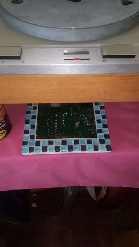
About 3 years ago , I ordered all the electrolytic , polyester and ceramic capacitors and resistors to replace the old ones on my Thorens TD125 MkI motor speed controller board . So I finally got round to doing it . The little mirror in front , for the stroboscope had also unglued itself , so I had to dismantle the front controls too , to re-glue that .
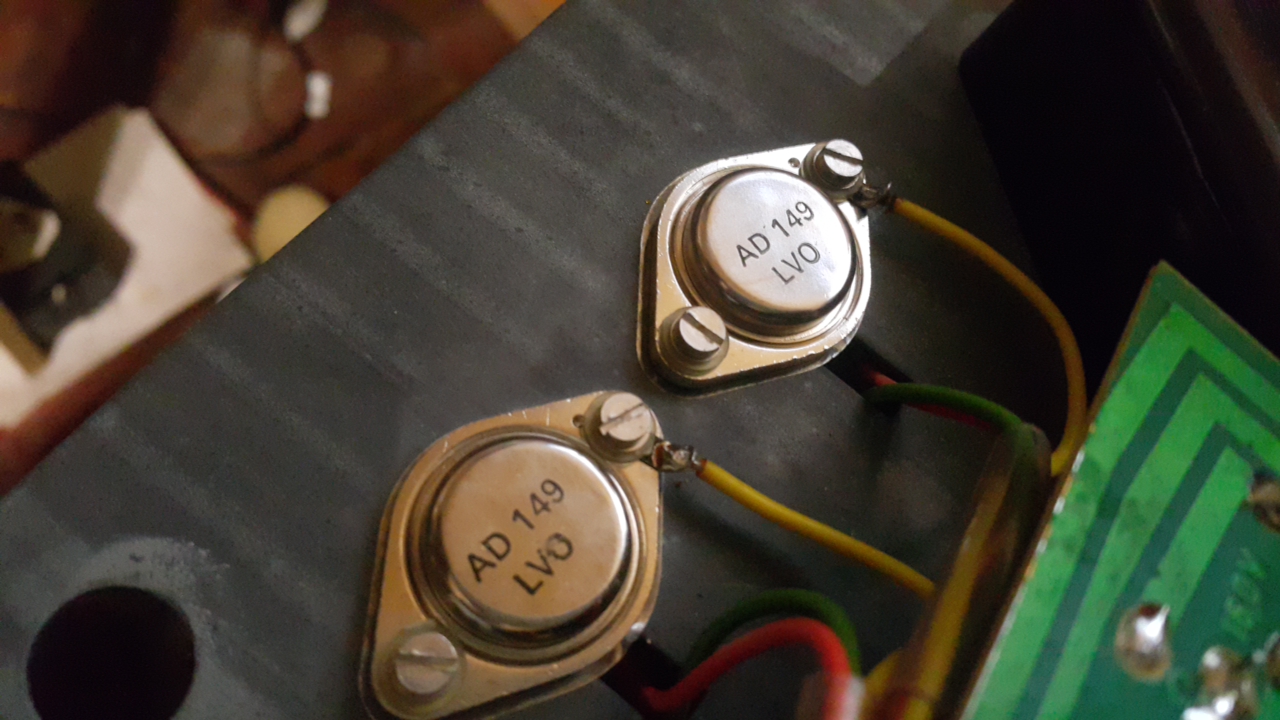
The TD125 already had had some work done by someone else , and all the small transistors appear to be new-ish . They are modern components , but I checked and compared the datasheets and they appear to be good equivalents with similar ratings to the old original components . The AD149's are the same as originals .
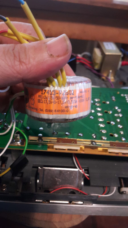
The original transformer was replaced with a toroidal with much higher voltage , which appeared to run quite hot , so I replaced that with an EI core version of lower voltage and higher current ( x4 current rating ) that I had lying here . For the record , the correct transformer's output on TD125 mk1 revision 2 is 12-0-12VAC , the earlier pcb uses a transformer with 2x 12-0 VAC taps . I'll post the 2 versions of the TD125 mk1 too .
Before the strobe would sway a bit when speed was set , and after a couple of hours of operation the motor would slow , and eventually just stop . The little toroidal would get toasty hot . Apparently core saturation makes voltage droop .
Here's the one that was there , I'll use it in a phonostage .
There are 3 primary potentiometers to set initial approximate voltages for 16 , 33 and 45 rpm . Then there are another 3 for setting speed dead-on right with pitch control pot in centre position .The controller mechanism is a Weinbridge oscillator . It's quite amazing . Once set and I apply pressure to the motor spindle , the voltage stays completely stable . I raised the plinthe with 4 cans of baked beans so-as to adjust the voltages and frequency for 16 , 33 and 45 rpm respectively , and "0" DC on output
Quite a pleasure having pulled it off successfully . ;D
I'm running the motor till tomorrow morning to see how everything holds up , then I'll start setting up suspension , etc.
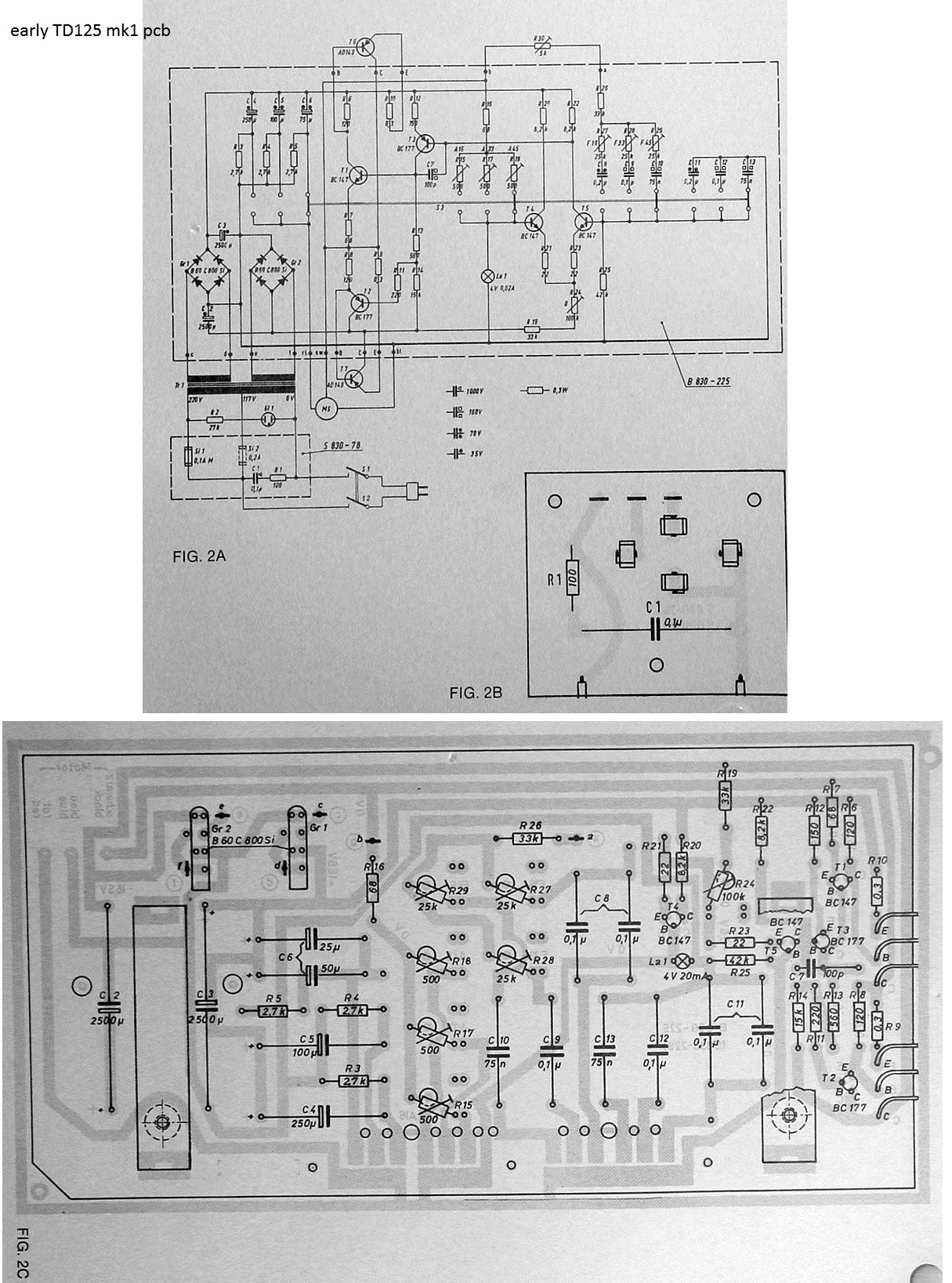
Here are the 2 different mk1 version schematics :
original mk1 pcb
revised mk1 pcb
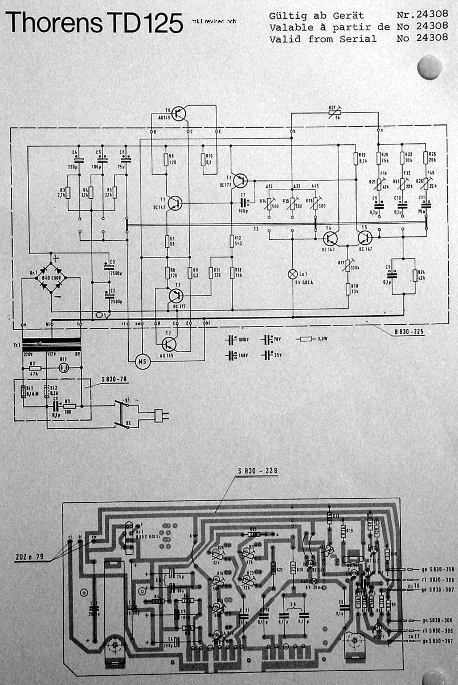
I could spot one error in the revised schematic . Look at the bottom right-hand corner of the schematic , parallel to C9 is 42k R24 . This is not indicated on the PCB image , and should be fitted to the right directly , of the lamp .
The TD125 already had had some work done by someone else , and all the small transistors appear to be new-ish . They are modern components , but I checked and compared the datasheets and they appear to be good equivalents with similar ratings to the old original components . The AD149's are the same as originals .
The original transformer was replaced with a toroidal with much higher voltage , which appeared to run quite hot , so I replaced that with an EI core version of lower voltage and higher current ( x4 current rating ) that I had lying here . For the record , the correct transformer's output on TD125 mk1 revision 2 is 12-0-12VAC , the earlier pcb uses a transformer with 2x 12-0 VAC taps . I'll post the 2 versions of the TD125 mk1 too .
Before the strobe would sway a bit when speed was set , and after a couple of hours of operation the motor would slow , and eventually just stop . The little toroidal would get toasty hot . Apparently core saturation makes voltage droop .
Here's the one that was there , I'll use it in a phonostage .
There are 3 primary potentiometers to set initial approximate voltages for 16 , 33 and 45 rpm . Then there are another 3 for setting speed dead-on right with pitch control pot in centre position .The controller mechanism is a Weinbridge oscillator . It's quite amazing . Once set and I apply pressure to the motor spindle , the voltage stays completely stable . I raised the plinthe with 4 cans of baked beans so-as to adjust the voltages and frequency for 16 , 33 and 45 rpm respectively , and "0" DC on output
Quite a pleasure having pulled it off successfully . ;D
I'm running the motor till tomorrow morning to see how everything holds up , then I'll start setting up suspension , etc.
Here are the 2 different mk1 version schematics :
original mk1 pcb
revised mk1 pcb
I could spot one error in the revised schematic . Look at the bottom right-hand corner of the schematic , parallel to C9 is 42k R24 . This is not indicated on the PCB image , and should be fitted to the right directly , of the lamp .