The circuit below was posted on diyaudio.com. I asked the guy who built it a few questions, but his answers were a bit glib. So I thought I'd ask here.
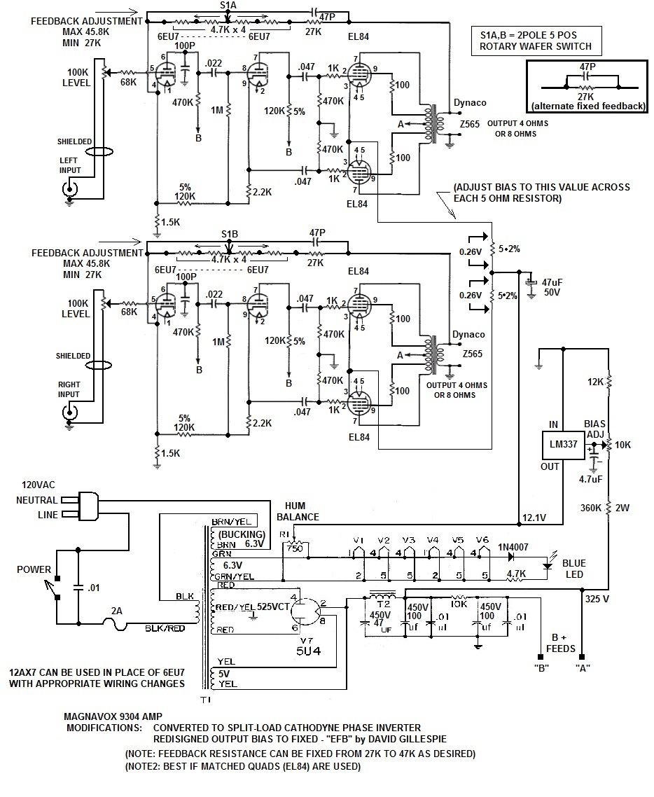
The first thing that struck me was the common resistor to ground for both pre and splitter. No cathode bypass, and won't there be a bit of feedback from the splitter into the pre as current in the splitter will change the pre cathode voltage? Maybe local feedback is the point?
On the anode side of the phase splitter there is a 120k resistor, but on the cathode side a total of 123.7k. It's not a big difference, but why unnecessarily introduce a possible imbalance?
The one that I really don't get though is that the 1M grid resisitor of the phase splitter triode doesn't go to ground, but almost to the same point as the in-phase output of the splitter. I get that the DC bias is set by the current through the 2,2k resistor, but isn't the AC signal then fed back onto the grid of the triode - positive feedback?
I quite like the power stage cathode bias - may use that in my EL84 amp