I have been very quiet on my Quad 33 and Quad 303 restoration threads mainly because I have been spending most of my spare time designing and installing a household sized water purification system.
The design incorporates the following components:
[list type=decimal]
[*]Rainwater harvesting to a tank farm.
[*]Condensation harvesting using an underground piping system.
[*]A hand drilled well point.
[*]Wetland system to purify the house's greywater.
[*]Irrigation system to distribute the purified greywater into the garden.
[*]A biogas digester to generate gas from the blackwater and liquid fertilizer from the digestate.
[*]A slow sand filter to purify the rainwater, condensation and well point water to potable standards.
[*]A water purification skid to control all of the above and distribute the potable water into the house.
[/list]
If anyone is interested I can keep posting as I proceed.
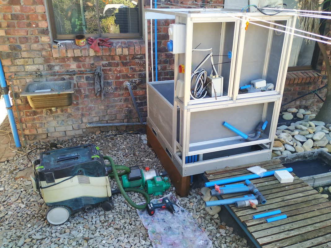
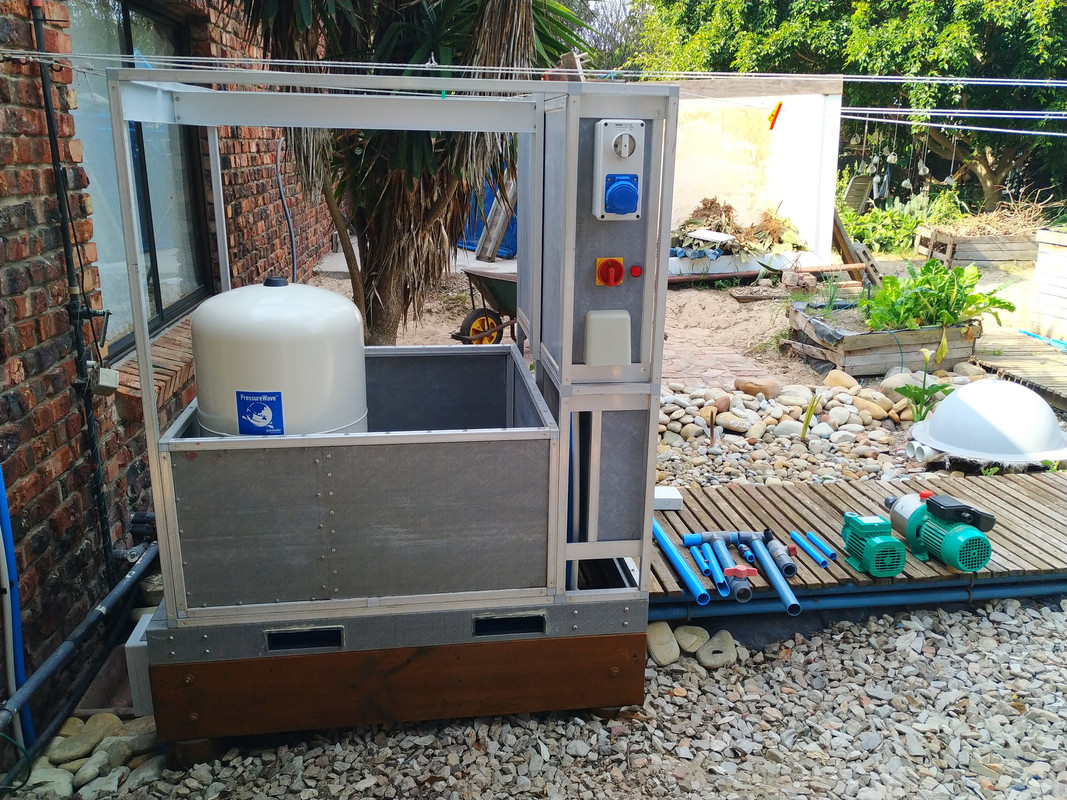
Here is the skid frame and cabinets assembled. Now busy with the internal pumps and piping. Then to tackle the electrical and control design.
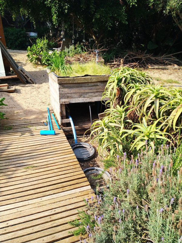
Revision 10 of the greywater wetland is almost complete.
The purified greywater is pumped from here into the garden using various pipe circuits.
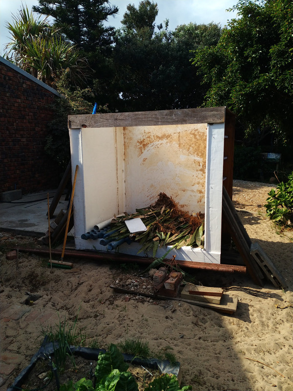
The slow sand filter being built. It was a experimental tank that was gifted to me to convert.
The design incorporates the following components:
[list type=decimal]
[*]Rainwater harvesting to a tank farm.
[*]Condensation harvesting using an underground piping system.
[*]A hand drilled well point.
[*]Wetland system to purify the house's greywater.
[*]Irrigation system to distribute the purified greywater into the garden.
[*]A biogas digester to generate gas from the blackwater and liquid fertilizer from the digestate.
[*]A slow sand filter to purify the rainwater, condensation and well point water to potable standards.
[*]A water purification skid to control all of the above and distribute the potable water into the house.
[/list]
If anyone is interested I can keep posting as I proceed.
Here is the skid frame and cabinets assembled. Now busy with the internal pumps and piping. Then to tackle the electrical and control design.
Revision 10 of the greywater wetland is almost complete.
The purified greywater is pumped from here into the garden using various pipe circuits.
The slow sand filter being built. It was a experimental tank that was gifted to me to convert.