People seem to respond to my rambling, so here we go again.
So managed to finally grab a set of Visaton's, been hunting for a while. I like their no-frills engineering and most importantly for me they're CHEAP, ish. And even better I managed to get the big boys, the Experience V20!
Link: http://www.visaton.de/en/bauvorschlaege/3_wege/experience_v20/index.html
Stats:
Rated power: 180 W
Maximum power: 300 W
Nominal impedance: 4 Ohm
Frequency response: 29 - 30000 Hz
Mean sound pressure level: 88 dB (1 W/1 m)
Cut-off frequency: 450 / 3000 Hz
Principle of Housing: Bassreflex
Net volume: 96 l + 5,5 l
Outer dimension height: 1300 mm
Outer dimension width: 300 mm
Outer dimension depth: 360 mm
2 x 8" Woofers, treated paper
2 x 5" Mids, treated paper
1 x 1" Soft dome

So I got the set that BiZKiT built back in 2013: http://www.avforums.co.za/index.php/topic,27524.0.html
Upon getting them home and down my 1000 stairs, after a quick visit to the chiropractor, I wanted to get them open to have a peek. Was worried about a comment in bizkit's thread that when he reworked them he noticed that some speakers were wired backwards.
As you can see in the Xover diagram the mids and tweets are 2nd order so they are supposed to be wired "backwards'
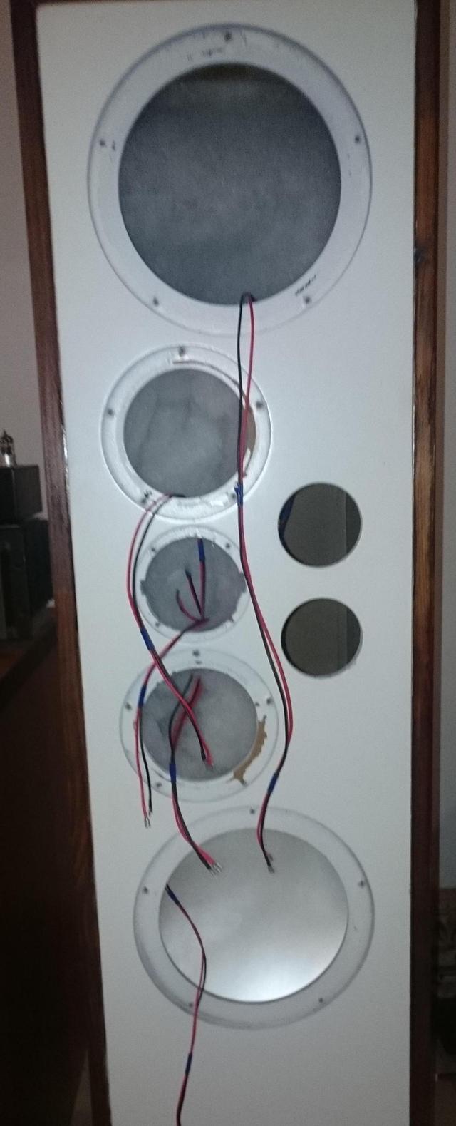
Well when I got the first woofer out I got a bit of a shock, to be frank it was a bit of a mess in there...
The internal wiring was that uber thick, clear cover, silver coloured :cr@p: (marked Jamo), it being so thick meant the soldering onto the Xover wasn't done very well, 2 joints actually broke off when I took the PCB out. While the spades were gold plated solder type, they weren't soldered on, the tabs were just bent over the wire. The enclosure was also stuffed with chunks of foam and cotton wool. :nono:
So I ripped it all out, got "batting" from Metro(along with my favourite rubber feet), cut it to the size and thickness of the original Visaton stuffing and re-damped the whole enclosure.
Then the hard part, re-doing all the internal wiring. Using 1.5mm hookup wire so I can through board solder, each spade will be soldered and heat-shrinked. 48 joints down and I'm halfway there:
So managed to finally grab a set of Visaton's, been hunting for a while. I like their no-frills engineering and most importantly for me they're CHEAP, ish. And even better I managed to get the big boys, the Experience V20!
Link: http://www.visaton.de/en/bauvorschlaege/3_wege/experience_v20/index.html
Stats:
Rated power: 180 W
Maximum power: 300 W
Nominal impedance: 4 Ohm
Frequency response: 29 - 30000 Hz
Mean sound pressure level: 88 dB (1 W/1 m)
Cut-off frequency: 450 / 3000 Hz
Principle of Housing: Bassreflex
Net volume: 96 l + 5,5 l
Outer dimension height: 1300 mm
Outer dimension width: 300 mm
Outer dimension depth: 360 mm
2 x 8" Woofers, treated paper
2 x 5" Mids, treated paper
1 x 1" Soft dome
So I got the set that BiZKiT built back in 2013: http://www.avforums.co.za/index.php/topic,27524.0.html
Upon getting them home and down my 1000 stairs, after a quick visit to the chiropractor, I wanted to get them open to have a peek. Was worried about a comment in bizkit's thread that when he reworked them he noticed that some speakers were wired backwards.
As you can see in the Xover diagram the mids and tweets are 2nd order so they are supposed to be wired "backwards'
Well when I got the first woofer out I got a bit of a shock, to be frank it was a bit of a mess in there...
The internal wiring was that uber thick, clear cover, silver coloured :cr@p: (marked Jamo), it being so thick meant the soldering onto the Xover wasn't done very well, 2 joints actually broke off when I took the PCB out. While the spades were gold plated solder type, they weren't soldered on, the tabs were just bent over the wire. The enclosure was also stuffed with chunks of foam and cotton wool. :nono:
So I ripped it all out, got "batting" from Metro(along with my favourite rubber feet), cut it to the size and thickness of the original Visaton stuffing and re-damped the whole enclosure.
Then the hard part, re-doing all the internal wiring. Using 1.5mm hookup wire so I can through board solder, each spade will be soldered and heat-shrinked. 48 joints down and I'm halfway there: