From StackExchange.
First let's consider this:
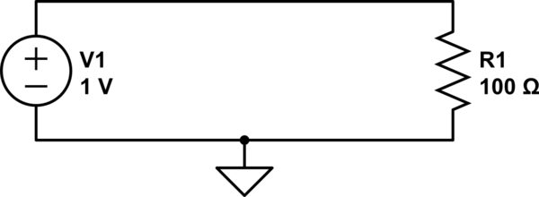
We can calculate the current through R1 with Ohm's law:
1V/100Ω =10mA
We also know that the voltage across R1 is 1V. If we use ground as our reference, then how does 1V at the top of the resistor become 0V at the bottom of the resistor? If we could stick a probe somewhere in the middle of R1, we should measure a voltage somewhere between 1V and 0V, right?
A resistor with a probe we can move around on it...sounds like a potentiometer, right?
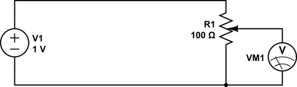
By adjusting the knob on the potentiometer, we can measure any voltage between 0V and 1V.
Now what if instead of a pot, we use two discrete resistors?
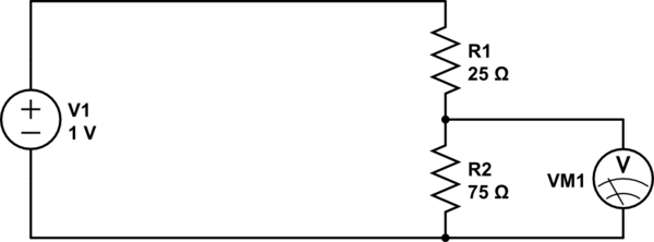
This is essentially the same thing, except we can't move the wiper on the potentiometer: it's stuck at a position 3/4th from the top. If we get 1V at the top, and 0V at the bottom, then 3/4ths of the way up we should expect to see 3/4ths of the voltage, or 0.75V.
What we have made is a resistive voltage divider. It's behavior is formally described by the equation:
V out =(R 2/ (R 1 +R 2)) ⋅V in
Now, what if we had a resistor with a resistance that changed with frequency? We could do some neat stuff. That's what capacitors are.
At a low frequency (the lowest frequency being DC), a capacitor looks like a large resistor (infinite at DC). At higher frequencies, the capacitor looks like a smaller resistor. At infinite frequency, a capacitor has to resistance at all: it looks like a wire.
So:
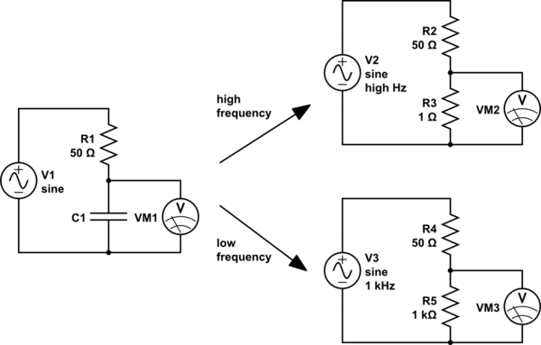
For high frequencies (top right), the capacitor looks like a small resistor. R3 is very much smaller than R2, so we will measure a very small voltage here. We could say that the input has been attenuated a lot.
For low frequencies (lower right), the capacitor looks like a large resistor. R5 is very much bigger than R4, so here we will measure a very large voltage, almost all of the input voltage, that is, the input voltage has been attenuated very little.
So high frequencies are attenuated, and low frequencies are not. Sounds like a low-pass filter.
And if we exchange the places of the capacitor and the resistor, the effect is reversed, and we have a high-pass filter.
However, capacitors aren't really resistors. What they are though, are impedances. The impedance of a capacitor is:
Zcapacitor =−j*(1/(2pi*fC))
Where:
?C is the capacitance, in farads
?f is the frequency, in hertz
?j is the imaginary unit, √−1
Notice that, because f is in the denominator, the impedance decreases as frequency increases.
Impedances are complex numbers, because they contain j . If you know how arithmetic operations work on complex numbers, then you can still use the voltage divider equation, except we will use Z instead of R to suggest we are using impedances instead of simple resistances:
V out =V in (Z2/( Z1 +Z2))
And from this, you can calculate the behavior of any RC circuit, and a good deal more.
First let's consider this:
We can calculate the current through R1 with Ohm's law:
1V/100Ω =10mA
We also know that the voltage across R1 is 1V. If we use ground as our reference, then how does 1V at the top of the resistor become 0V at the bottom of the resistor? If we could stick a probe somewhere in the middle of R1, we should measure a voltage somewhere between 1V and 0V, right?
A resistor with a probe we can move around on it...sounds like a potentiometer, right?
By adjusting the knob on the potentiometer, we can measure any voltage between 0V and 1V.
Now what if instead of a pot, we use two discrete resistors?
This is essentially the same thing, except we can't move the wiper on the potentiometer: it's stuck at a position 3/4th from the top. If we get 1V at the top, and 0V at the bottom, then 3/4ths of the way up we should expect to see 3/4ths of the voltage, or 0.75V.
What we have made is a resistive voltage divider. It's behavior is formally described by the equation:
V out =(R 2/ (R 1 +R 2)) ⋅V in
Now, what if we had a resistor with a resistance that changed with frequency? We could do some neat stuff. That's what capacitors are.
At a low frequency (the lowest frequency being DC), a capacitor looks like a large resistor (infinite at DC). At higher frequencies, the capacitor looks like a smaller resistor. At infinite frequency, a capacitor has to resistance at all: it looks like a wire.
So:
For high frequencies (top right), the capacitor looks like a small resistor. R3 is very much smaller than R2, so we will measure a very small voltage here. We could say that the input has been attenuated a lot.
For low frequencies (lower right), the capacitor looks like a large resistor. R5 is very much bigger than R4, so here we will measure a very large voltage, almost all of the input voltage, that is, the input voltage has been attenuated very little.
So high frequencies are attenuated, and low frequencies are not. Sounds like a low-pass filter.
And if we exchange the places of the capacitor and the resistor, the effect is reversed, and we have a high-pass filter.
However, capacitors aren't really resistors. What they are though, are impedances. The impedance of a capacitor is:
Zcapacitor =−j*(1/(2pi*fC))
Where:
?C is the capacitance, in farads
?f is the frequency, in hertz
?j is the imaginary unit, √−1
Notice that, because f is in the denominator, the impedance decreases as frequency increases.
Impedances are complex numbers, because they contain j . If you know how arithmetic operations work on complex numbers, then you can still use the voltage divider equation, except we will use Z instead of R to suggest we are using impedances instead of simple resistances:
V out =V in (Z2/( Z1 +Z2))
And from this, you can calculate the behavior of any RC circuit, and a good deal more.