I am trying to get an Acoustic Research table together. Yesterday I managed to get everything plugged in and the motor runs very rough. I put a little oil on the spindle and it runs a little better but still rather rough.
I am trying to figure out how the motor circuit works.
From what I can see the circuit has a cap for phase shift and then runs through another capacitor to achieve the desired voltage drop (from 220v to 115v). There is also another resister on the board that I think has something to do with the switching circuit... Basically the switch is a 6 pin 'rocker type' switch. So in the on position both windings of the motor get electricity. In the off position it looks like the power is shorted through that tiny resister :thinking:
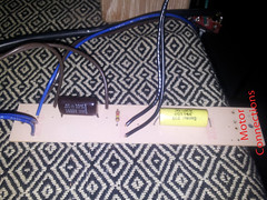
Acoustic Research Motor Circuit Board - top
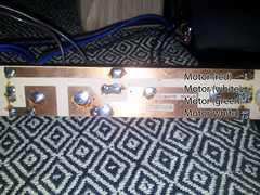
Acoustic Research Motor Circuit Board - bottom
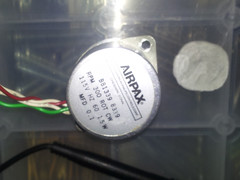
Acoustic Research Motor - Airpax
I was a little worried that one of the windings on the motor was toast so I removed the motor from the board and checked the resistance of each winding. They both measure the same 9.5K Ohms.
I then tried the motor with a 220\110v transformer and a 0.1 uF cap doing the phase shift. It definitely runs a whole lot smoother than with the factory circuit board. Not perfect but acceptable (acceptable being measured off my experience with other AC motors from turntables).
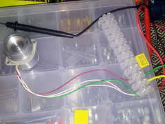
Acoustic Research Motor - Geddon type circuit
But. I want to use the original board.
Any thoughts? Change the three components on the original board and 'try again'? Anyone know what the value of the big yellow cap is? Any other thoughts :help:
I am trying to figure out how the motor circuit works.
From what I can see the circuit has a cap for phase shift and then runs through another capacitor to achieve the desired voltage drop (from 220v to 115v). There is also another resister on the board that I think has something to do with the switching circuit... Basically the switch is a 6 pin 'rocker type' switch. So in the on position both windings of the motor get electricity. In the off position it looks like the power is shorted through that tiny resister :thinking:
Acoustic Research Motor Circuit Board - top
Acoustic Research Motor Circuit Board - bottom
Acoustic Research Motor - Airpax
I was a little worried that one of the windings on the motor was toast so I removed the motor from the board and checked the resistance of each winding. They both measure the same 9.5K Ohms.
I then tried the motor with a 220\110v transformer and a 0.1 uF cap doing the phase shift. It definitely runs a whole lot smoother than with the factory circuit board. Not perfect but acceptable (acceptable being measured off my experience with other AC motors from turntables).
Acoustic Research Motor - Geddon type circuit
But. I want to use the original board.
Any thoughts? Change the three components on the original board and 'try again'? Anyone know what the value of the big yellow cap is? Any other thoughts :help: